Thursday, April 28, 2022

A First Foray Into Kumiko, Part 2: More Jigs

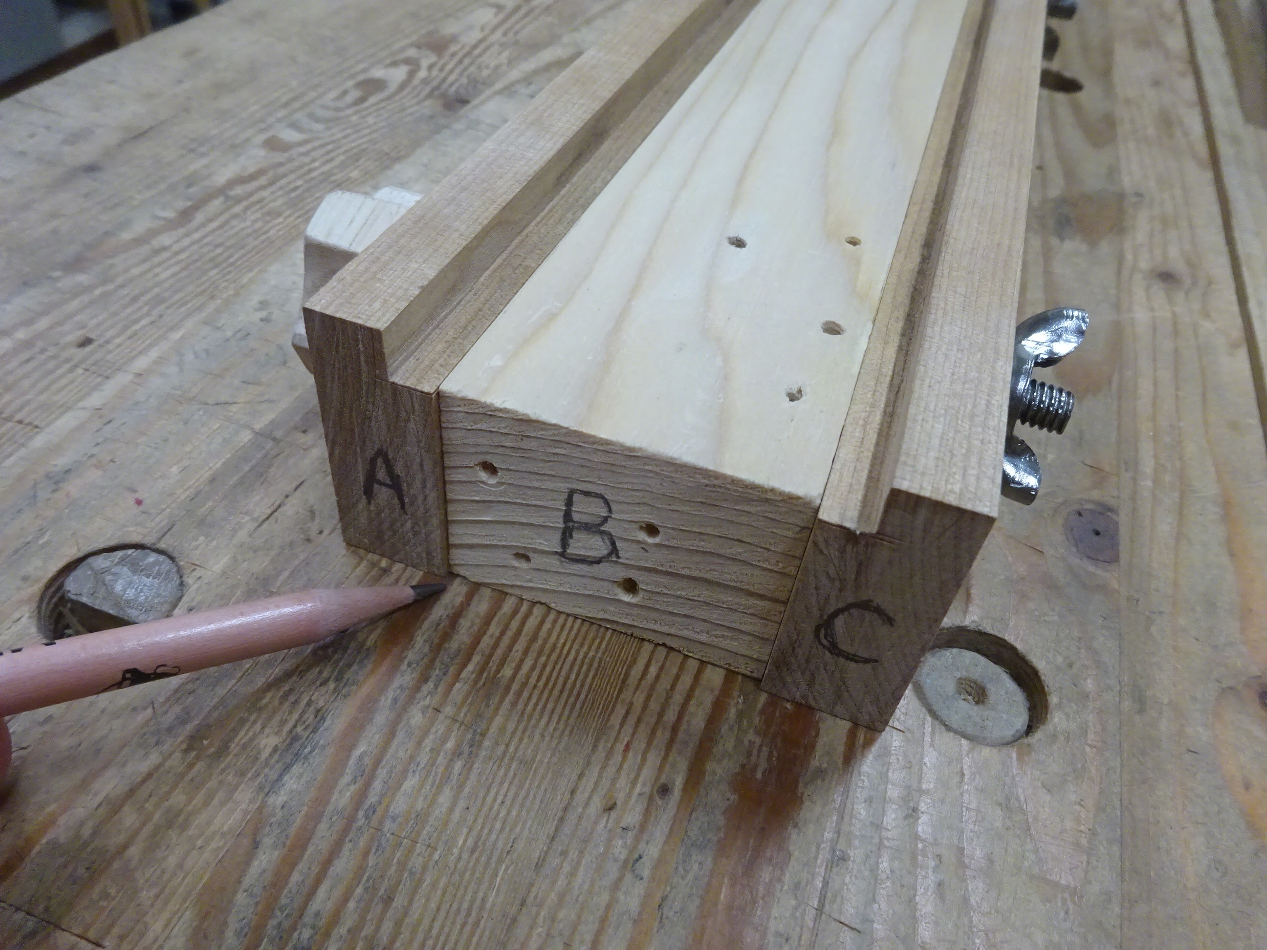
Last time I wrote about the thickness planing jig.  The second jig needed for the square-based kumiko is a cross-cutting jig.  It's basically a tiny miter box for 90° cuts.  The jig includes a 3/4" x 3/4" piece glued to a 3/4" x 2 1/2" piece.  A couple of 90° saw kerfs are made into the smaller piece, as accurately as possible.  These kerfs guide the saw when making the half-lap joints that make up the frame of square kumiko designs.

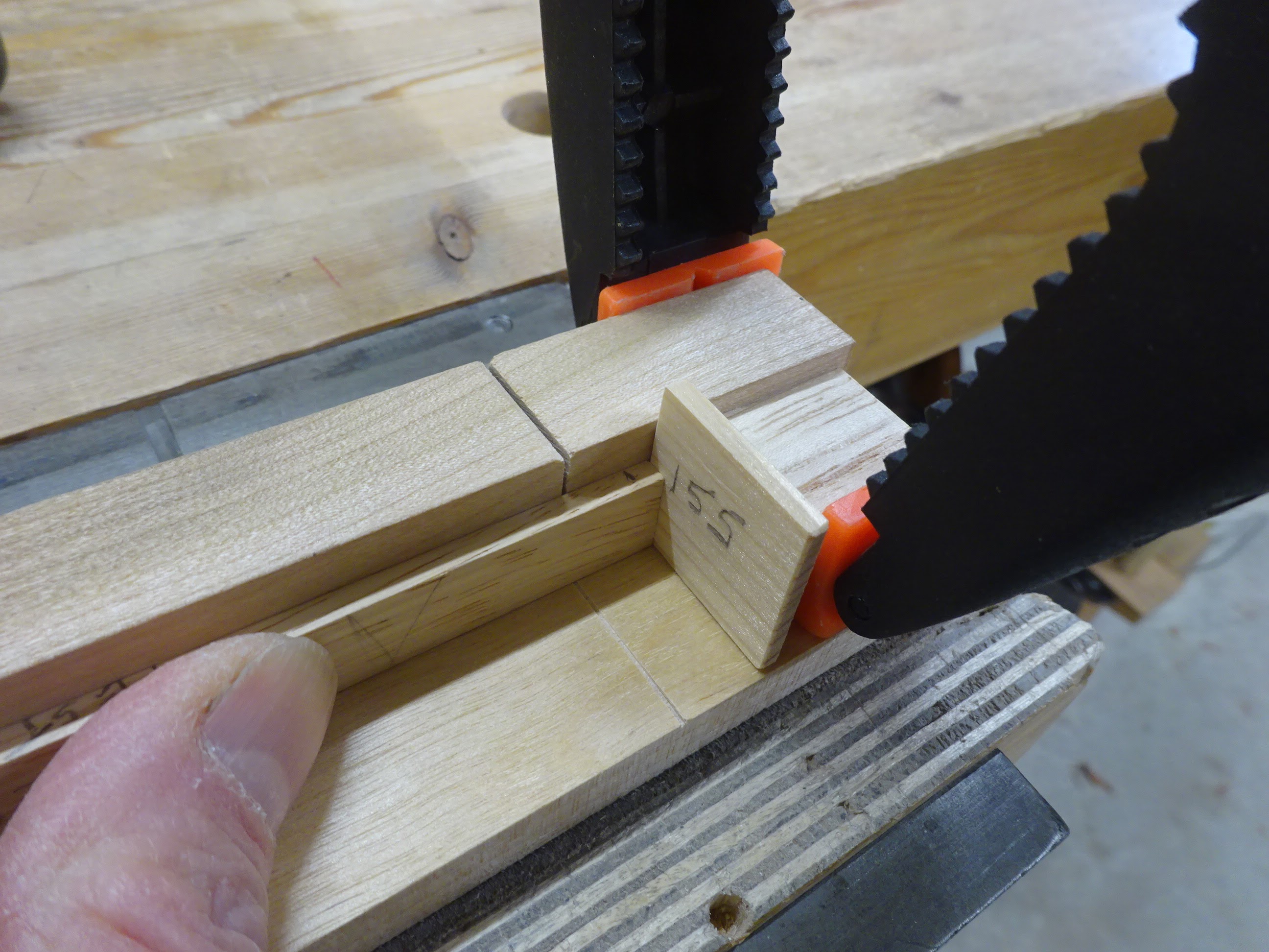
The cross-cutting jig, with stop block clamped in place and a 0.155" spacer.
The spacer adjusts for the saw kerf to make a lap joint about 0.139" wide.

With spacer in place, butt the workpiece against the spacer ...

Cut half way down ...

Then remove the spacer, butt the stock against the stop block, and make another cut

At first, I removed the waste with a 1/8" chisel, but later found it easier to poke it out with a thumb nail.  Here's an early test fit of a stick into its half-lapped partner.

Testing the fit

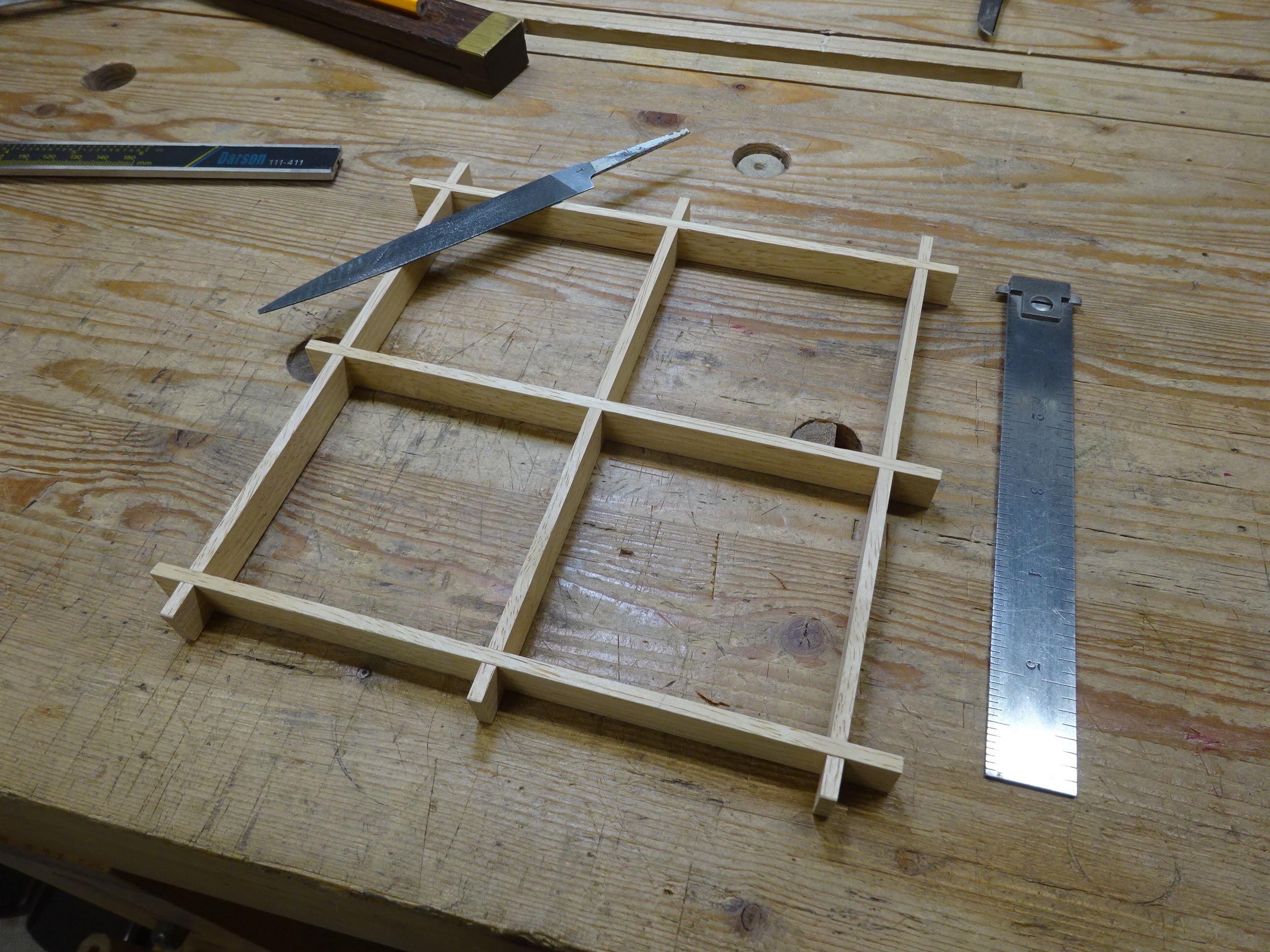
In the first pic of this jig above, you'll notice there are two kerfs in the top piece.  This was the spacing I chose for my first trial kumiko.  After making a few more test cuts, I fit together a frame.

The frame fit together nicely, but a small file "sweetened" the fit of  a few tight joints.

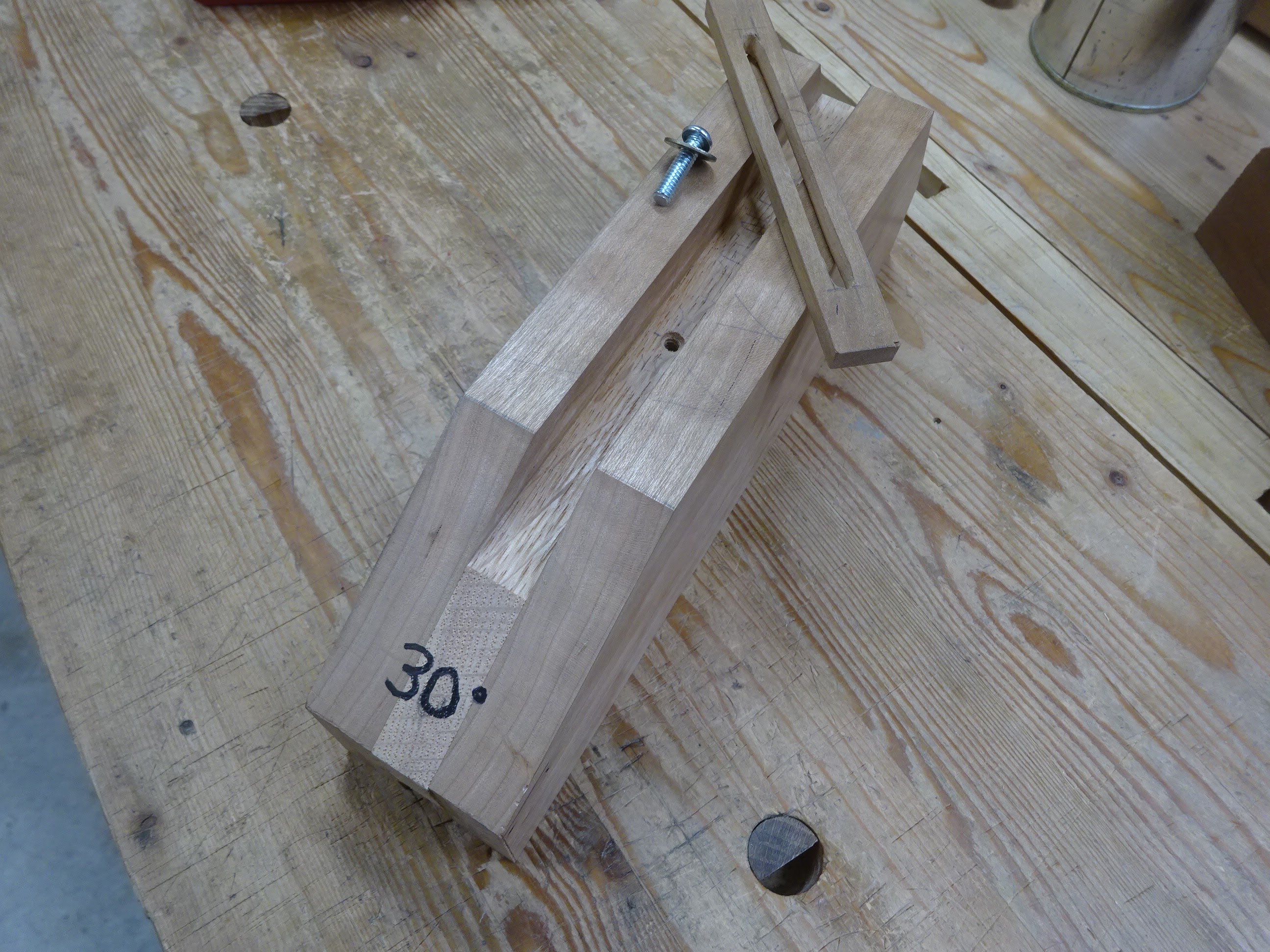
The next step in my first kumiko pattern is to fit pieces into the diagonals of the four smaller squares, radiating out from the overall center.  This leads us to the third jig that is needed, which allows precise angles to be cut on the end of a workpiece.  The jig is a chunk of wood, about 2" thick, with a groove running down the center of one edge.  An adjustable stop slides in this groove and can be locked down to allow repeatable cuts.  The end of the chunk of wood is sawn and planed precisely to the angle needed.

The jig and accessories

Stop block locked down to allow just a little of workpiece to extend beyond the 45° angle front

I made some tiny wedges to hold the workpiece tight against one wall

Also have 22 1/2° and 67 1/2° angles on the other end

Before I forget to mention it, the groove is about 5/8" deep.  It needs to be deep enough so that, after an angle is sawn and planed on the end, there is enough reference surface on which to register a block plane or chisel when making cuts.  This seemed about right.

In use, I clamp it in a vise and use either a chisel or block plane to shave a little bit off the end of a workpiece.

The jig clamped in a vise

To use the jig, a workpiece is placed in the groove, its back end butted up against the adjustable stop.  Then a chisel or block plane can be used to trim the end of the piece at the proper angle.  Turn the piece over and put the angle on the other side and you get a perfectly centered point on the end of the piece.

Trimming the end of a test piece

I cut two small shims from brass shim stock, one of 0.005" and one of 0.010" thickness.  These allow very fine adjustment of parts to close in on the right length.

Arrow shows placement of thin shim that pushes out the workpiece 0.005"

I later made improvements when making another jig for hexagon-based kumiko.  The jig shown above was made form VERY soft redwood.  When trimming a workpiece with a chisel, often the far end of the piece would blow out because there wasn't good enough support.

Arrow shows where blowout was possible

So the next jig was made from hardwoods.  I laminated 5/8" oak between two 3/4" pieces of cherry.  The hardwood also allowed me to tap a hole in the oak so that a machine screw could be used to lock the sliding stop in place.  The original jig had three holes for further adjustability of the stop, but so far I've only used the middle one.  So I put only one in the newer jig.

Jig for hexagon-based kumiko

Because this jig was laminated, I had to make sure the top edges of the sides were aligned properly and also that the bottom of the groove was parallel to those trued up cherry edges.  I used a router plane to do the latter step.

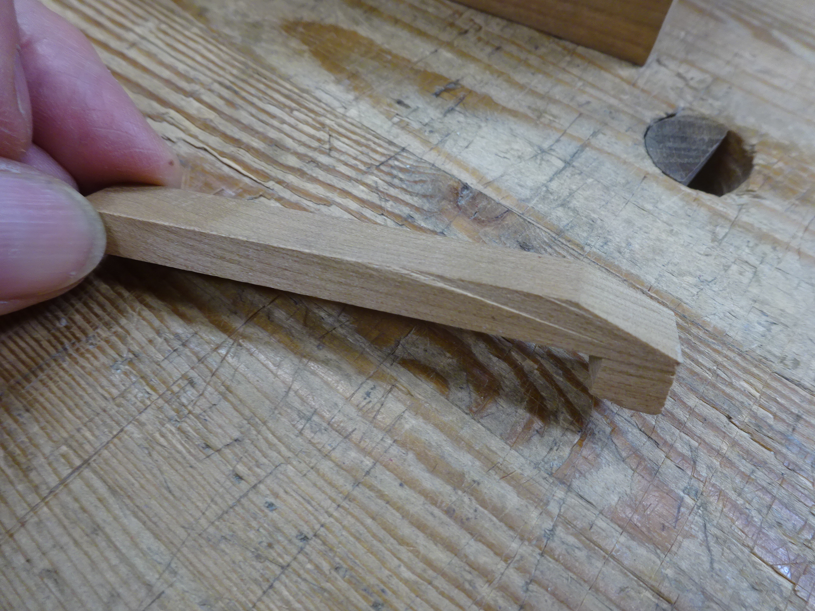
For this new jig, I made a couple different helpers to keep the workpiece stable.  One was a small wedge, a scrap piece of kumiko stock with a bevel on one end.  This bevel fits into the gap between workpiece and side of the groove and can be used like a lever to force the piece against the far wall.

The little wedge

Levering the workpiece against the far side of the groove

I also stole something from a Fine Woodworking video - a little hold-down that presses the workpiece down to the bottom of the groove.

The hold-down ...

... and how it is used

No doubt more than most people want to know about these jigs.  But it helps me to write it down.  Next time I'll get into the actual making of square kumiko patterns.

Thursday, April 21, 2022

A First Foray Into Kumiko, Part 1: The Jig Is Up

Here's another bucket list item.  I've wanted to try kumiko for a long time.  Geometric patterns appeal to me and this definitely scratches that itch.  It's not as hard as I thought it might be - especially the patterns based on squares.  You just have to be meticulous - and have a few jigs that allow for precise cuts.  I used scrap pieces of wood, planed accurately to 1/2" x 1/8+".  My thickness was actually about .139", so that I could fit a 1/8" chisel to remove the half-lap waste without worrying about cracking the keeper wood (turns out 1/8" thickness would have been fine).

My first kumiko

Three jigs are involved in making this particular pattern.  First is a thicknessing jig, second a cross-cutting jig for small parts and third, an angle trimming jig.

Kumiko starts with accurately preparing the sticks.  I had made a thicknessing jig some years ago, but wanted to make a new one with greater accuracy and adjustability and I saw this design on YouTube (sorry, can't seem to find it again to provide a reference).

This thickness jig was made for my trusty #4

Three main parts: sides A and C, and base B

The sides are adjustable using slots over hanger bolts screwed into the base

Here's the key to this design.  The rabbets on the inside top edge of the side pieces are cut so that the distance from the bottom of the side to the bottom of the rabbet is exactly the same as the height of the base.

Here, the side and base are both bottomed out on the benchtop
and the bottom of the rabbet is exactly co-planar with the top of the base

When cutting the rabbet, don't plane it to full depth, but get close.  Then clamp the base and side together with their bottoms precisely lined up, and with a chisel referencing on the base, trim the rabbet to proper depth.  This allows for easy setting of an exact dimension when planing to specific thickness.

Using a set-up block to set the thickness precisely

1/2" set-up block used to set the thickness that will be planed

Exact!!

The last part of the jig is the planing stop at the front.  It's just a chunk of scrap wood with a slot in it for adjustability, though I've not yet needed to adjust it.  It needs to be set so that its highest point is above the base but lower than the rabbets.

The stop at the front end (ignore the two other holes)

The stop doing its job in holding the workpiece while planing

When making a jig like this, you have to take into account the width of the plane you intend to use with it.  The distance between the left side and right side vertical rabbet walls should be slightly greater than the width of your plane.

Here's an interesting feature.  You can imagine that if the jig is used on the benchtop and if the sides weren't tightened securely, they might start dropping while planing a stick.  When planing a stick to 1/2" thickness, enough of the base sticks down below the sides that you can clamp the base in the vise with the bottoms of the sides resting on the vise chops.  This reduces the chance of the setting gradually changing while you plane.

Thicknessing jig in the vise
(here, it's only set for 1/8"+ thickness, but you get the idea)

When planing the 1/8"+ pieces, I had it on the benchtop using my regular planing stop to keep the jig from shooting off the end of my bench.  I cinched down pretty hard on the nuts holding the sides in place and I had no issues with any drift in the setting as I planed.

Finally, there is one minor annoyance that I'll fix when I get the chance.  The vertical walls of the rabbets can be angled or chamfered so that its easier to get the plane in and out of the jig.  My plane doesn't have much side-to-side play in the jig, and there have been times when it was frustrating to get the plane back into the jig to sit on the rabbets.

This is getting long, so I'll write about the other jigs next time.

Thursday, April 14, 2022

Unknown Maker Drawknife

This drawknife was thrown in for free when I bought the Millers Falls #67 router plane a few weeks ago.  It had a lot of pitting, but I took it to see if it could be brought back to life.

New-to-me drawknife

There wasn't much in the way of markings.  I wish I could have made out the maker's name.

"9 IN"

Unfortunately the metal was too corroded to read the maker mark.
Looks like the last few letters are "...WICO", or "...W CO", or maybe "... NICO"

There was a LOT of pitting on this knife.

Bevel side

Flat side

The blade was bent as well as twisted.  But it was surprisingly easy to fix those things.  I held the blade in a vise and bent and twisted it back into much better condition.

Here's something interesting.  When I started cleaning up the metal, I filed some grunge away on the side of the blade and was surprised at what I saw.

It looks similar to very old plane irons that have a thin piece of
harder steel forge welded to softer iron

I've never heard of this technique used for drawknife blades.  It's probably just a single piece of steel.  But there might be more evidence later when I've sharpened the bevel.

On to sharpening.  I used the hand-crank grinder to grind a new bevel.  A fair amount of metal had to be removed as there were a lot of nicks in the edge.

Action shot of grinding.  Look at those sparks.  Ooooh, sparks ...

In the picture, a clamp is holding a 3/8" dowel to the tool rest.  The dowel is flattened on the bottom (so it doesn't roll) and has a notch on top near the front where the back of the knife rests.  That allowed me to adjust how the bevel was presented to the grinding wheel.  It was important due to the curvature of the knife's 9-inch edge.

Also ground the back to create a slight hollow

The slight hollow made it easier and quicker to flatten the back
with sandpaper wrapped around a block

To sharpen the bevel, I clamped the knife to the workbench, raised up on a couple of sticks.  Then used the sandpaper and block again to work the bevel.  I went through several grits, ending with 600 (I think).

Sanding the bevel at about 25°.
Later gave it a secondary bevel of about 30°

Stropped the bevel and back to get a nice edge

OK, the following pictures show evidence of a forge-welded blade.  If anybody knows whether or not this was ever done with drawknives please let me know in the comments.

See that "seam" in the bevel?

Closer picture: could that be the seam between hard steel and soft iron?

Anyway, now I've got another working drawknife.  And it was thrown in for free with the router plane.  Can't complain.

Update: This week, I got a chance to use this drawknife and it cuts beautifully and feels great in the hands!!

Thursday, April 7, 2022

Charles Morrill Saw Set

A few weeks ago at an estate sale I found this old saw set by Chas. Morrill.  It was looking pretty rough from lack of use, but cleaned up nicely.  The lower handle has something like JB Weld on it, but I can't figure out why since there are no evident cracks.  Perhaps it was to make the handle more comfortable for the user.

Charles Morrill saw set

Inside of upper handle

Inside of lower handle

Top side of business end

Bottom side

The other markings on the set are as follows:

Bottom of lower handle:
CHAS.
MORRILL
REG U.S. PAT. OFF.
NEW YORK

Right side of lower handle:
TRADEMARK
(APEX in TRIANGLE)
REG. U.S. PAT. OFF.

Left side of lower handle:
Patented
Feb. 23 1897
July 1 1902

"OMO" symbol with plus signs in the O's (may have been some kind of trademark) 

On the main body: 15 (who knows, maybe a saw set number)

I took it apart to clean it, which involved knocking out a pin that holds the lower handle in place.  That always makes me nervous.  But the parts all cleaned up nicely.

Parts is parts

Here are a couple pictures of the "plunger", the part that pushes a saw tooth against the anvil (wheel).

The plunger

Front end that contacts a saw tooth

When I took it apart, there was one part I couldn't remove: the adjustment for different size saw teeth.  It was stuck hard.  I oiled it several times and used a metal prod to pry it loose from the front wall of the main body.  Eventually it could rotate to adjust for different tooth sizes, but I still couldn't remove it.

The wheel (anvil) that adjusts for tooth size: note how the bevel
on the side facing the camera gradually changes around the wheel

This round pin is somehow involved in keeping the wheel in place,
but I didn't want to try tapping it out for fear of breaking it

After a thorough cleanup, I could see the markings on the wheel much better.  The following six pictures show the markings as the wheel is rotated.  Note that these pictures are taken of the underside of the tool.

... 8    10    12 ...
... SAW   POI ...

... 12    14    15...
... POINTS ...

... 15    13    11 ...
... TS TO INC ...

... 13    11    9 ...
... TO INCH |||||||| ...

... 9    7    5 ...
... |||||||||||||||| ...

... 4    6    8 ...
... |||||||||||||||| SAW ...

And we're back to the beginning.  So if I start from the 4 ppi, the numbers are: 4, 6, 8, 10, 12, 14, 15, 13, 11, 9, 7, and 5.  It's interesting that they went up to 15 and then started down again.  But I guess that makes sense - you don't want a "cliff" on the anvil between the smallest and largest settings.

In the following pic, I'm simulating the use of the set on my largest rip hand saw that has about 5 1/2 ppi.  The wheel setting is a little left of the 5 (towards the 7).

Choosing the right setting for tooth spacing

Here's another interesting feature of this saw set.  When the set is placed on a saw, there is a machine screw on the underside that tightens against the saw plate so that the set won't pivot up or down while setting the teeth.

Side view of saw set on a saw.  Note the screw pinching the saw plate
to the center of the adjuster wheel.  It has a lock nut to keep the position.

Well, that's it.  This is a very nice saw set.  It cleaned up nicely and works perfectly.  I'm not sure I would use it on my smaller saws with 12-15 ppi because the face of the plunger seems too large for that.  But I've got it for the larger saws.