Friday, December 27, 2019

Side Table, Part 6: Glue-up and Feet

I had been dreading the glue-up for weeks.  I went over it many times in my head and it wasn't too bad.  But I did have two screw-ups.  As everyone knows, it's tough to get pictures during a glue-up because you're rushing to get things in clamps before the glue sets.  So there are no in-progress pics.
Clamped up
The sequence went like this:
  1. The day before the main glue-up, glue the drawer dividers. The tenons of the runners (the front to back members) get glued into the front rail mortises, but the rear runner tenons stay dry in their mortises.
  2. Glue the left side dovetails to the bottom pins.
  3. Glue the right side dovetails to the bottom pins.
  4. Disassemble the right side dovetails because you forgot to glue the drawer dividers into the left side dadoes first.  Rrrrrrr!  Curse loudly.
  5. Glue the drawer dividers into the left side dadoes.  Glue only goes where the rails will fit the dadoes - the runners are free to float in the dado.
  6. Glue the right side dovetails into the bottom right pins and the drawer dividers into the right side dadoes.
  7. Glue the top rails into the half-blind dovetail sockets at the top of the sides.
  8. Get some clamps on the whole.
  9. Check for square and set up a Spanish windlass (the twisted rope) to pull it into square.  It was out a little more than 1/16".
  10. Fit the frame and panel back into the rabbets to help keep the carcase square.
  11. Get a couple more clamps on to seat the dividers more fully in their dadoes.


Another view
Although this was stressful, it seems to have come out fine.  I messed up one other thing.  The rear top rail is in backwards, and because of that, the back edge of that rail does not line up with the rabbets and leaves a gap between the rail and the F&P back.
Mind the gap!  That's not supposed to be there, but no big deal.
OK, with that done I focused on the bracket feet.  From the picture below, you can see that each foot is made from two mirror image parts that are mitered and glued at the corner.  The shape was first made on a thin plywood template.

I wanted the feet to be made from 1" thick poplar, but was afraid that might look too clunky.  So I experimented with 3/4" stuff and compared.  In the end, I stayed with 1" material.

The 3/4" thick foot glued up and clamped, the template and the four 1" blanks that will become feet
In making these parts, there was another "order of operations" question that I had to think about.  To cut the miters first or shape the profile first, that is the question.
Here's one that I shaped first, then sawed (and planed) the miter second.
The vise had plenty of grip on the thin end.
I tried it both ways and they both can be done, but when planing the miter I found it better to clamp the unshaped blank in the vise for a better grip.
One way of planing the miter
A much better way of clamping the piece for planing the miter
If I shaped the profile first, there's less for the vise to hold, but it can still work
The miters turned out easier to do than I thought they might be.  I sawed most of the waste away, then planed to layout lines and checked the angle with a combination square.  As it turned out, my glue-ups were not even close to square, so I didn't really need the miters to be perfect 45° cuts.  I ended up planing the outside surfaces square to each other after the glue dried.

The shaping was done first with coping saw, then with chisels/gouges and finally rasps and files.
The Knew Concepts coping saw works great
It's nice to have an incannel gauge for the concave areas
Here's how the feet will look, minus glue-blocks
I'm installing glue-blocks on the inside surfaces of the feet.  These will provide extra surface area when gluing the feet to the underside of the carcase and also a place to drive a couple screws.  I also drilled holes through the feet for screws, though the half-feet at the back of the carcase will be over a rabbet, so I didn't think the screws would be a good idea there.
Glued the horizontal blocks first, then the vertical block later.
The vertical block is shaped so it won't easily be seen.
Feet with glue blocks: foot at left is a back foot with only one screw hole through the foot
And here's a foot standing upright (leaning against another one).
How the foot will look
Next up: drawer making and fitting.

Thursday, December 19, 2019

Side Table, Part 5: Frame and Panel Back

The rear of the carcase will be enclosed with a frame and panel back that fits into the dadoes in the sides and bottom.  This is definitely more work than is necessary, but it's the way it was done in "The Joiner and Cabinetmaker".  And it looked like fun.
The frame components
All frame components are 1 1/2" wide, 3/4" thick poplar.  The outside stiles are cut a couple inches extra long to allow for "horns" that will be cut off later.  The horns make mortising close to the end of a stile a bit safer.
One mortise completed.
In the book, Schwarz discusses whether to chop the mortises first or to plough the grooves first.  There are pros and cons each way, depending on your tools and your comfort zone.  I chose to chop the mortises first.  These are through mortises, so I can mark both sides of the stile and those marks give me a positive line to pare the mortise wall to after chopping.

Then it was a matter of breaking out the old Ohio Tool wooden plough plane and grooving the pieces.
Groovin', on a sunny afternoon ...
Once the outside stiles were mortised, the top and bottom rails received tenons and a dry-fit allowed me to get the shoulder lines of the center stile.
Stiles and rails dry-fit - rails not yet grooved
Marking the shoulder line of the center stile with a knife nick
After locating the center stile with pencil marks on the rails, I marked the rails for the mortises and chopped and pared to the lines.
The center stile dry-fit to the frame, middle rails ready for marking their locations
Then I cut the tenons on the center stile and fit them to the mortises, and added the grooves to all three pieces.  The center stile got grooves on both edges.

The middle rails got stub tenons to fit in the grooves of the stiles.  The shoulder lines were determined the same was as for the center stile, then the shoulders were cut, the waste split away and the short tenons fit to the grooves.
The completed frame dry-fit
I had an off-cut poplar board that was big enough to get all four panels - I just had to re-saw it to get the 5/16" to 3/8" thick pieces.  The board had a pretty good twist in it and wouldn't have been good for much, but the smaller pieces were more manageable.  The re-sawing gave me nicely matched panels.
First dry-fit with the panels
The picture above is the inside of the back, so the panels don't look matched.  It took a fair amount of trial fitting to get everything to fit right, but eventually it all worked out.  Note that the panels are raised slightly using a simple bevel to get the edges to fit into the grooves.
The outside face.  A shame it won't ever be seen, but I'll know it's there.
After gluing it up, I cut off the horns and fit it to the back of the cabinet.  I had made the back about 1/16" too wide and tall to fit in the rabbets so that I could plane to fit later.  After a bit of planing, I got a nice fit.
And here it is, set into the rabbets of the dry-fit carcase
Next up: the feet and glue-up.

Thursday, December 12, 2019

Side Table, Part 4: Drawer Dividers

The three drawers will be separated by frames that are housed in dadoes in the carcase sides.  The front and back members of the frames (I'm calling them the "mid-rails") are poplar and have mortises that take the tenons of the side members.  The side members of the frames are the drawer runners and they are made from maple.
Carcase showing drawer dividers
The dadoes that are needed
I carefully laid out the dadoes, first in pencil and later with a knife.  Once again, the size of the sides made this challenging.  I wanted the dadoes to be located perfectly evenly on both sides.  So with the case dry-assembled, I used a short stick cut to just the right length to get the upper dado locations relative to the case bottom.  I marked at both the front and back of the side and then connected the knife nicks using a straightedge.  I cut the stick down to just the right length to mark the lower dado locations.
Used a stick to locate a knife nick at the front and rear of the side,
then connected the nicks with a knife line to mark one side of the dado
Cut the stick shorter to mark the lower dado
Marked for dadoes
BTW, these are stopped dadoes, ending 1/2" from the front edge of the case.  Now it was chopping time.  Man, that was a lot of chopping.  It's almost 23" of 3/4" wide dado.  I didn't get a picture of it, but after chopping a large angled notch, I used the mid-rails to find the location of the other side of the dado.
After lots of chopping, finished with a router plane
Even though I thought I had chopped vertically, I still needed to pare the walls
Got a decent fit
The mid-rails and runners are connected with mortise and tenon joints.  I had planed the runners about 1/32" thicker than the mid-rails so that I could plane them down after cutting the mortises and tenons.  I usually get a slight step in a m&t joint line, so I thought I'd make the runner slightly thicker and plane it down to meet the rail.  Anyway, the mortises and tenons went well.
Rail (left) marked for mortise, runner marked for tenon
I got to use the dedicated 1/4" mortise gauge that I made a few months ago
I chopped the first mortise, but for the rest of them I bored out most of the waste before finishing with a chisel.  I used the "ring" trick to ensure I was boring perpendicular.  Here's the thing about the ring trick - it only works if the workpiece is perfectly vertical.  So you need some method to verify this.
Clamping the rail vertically, checking with a level
I also spring-clamped a couple of sticks to the sides of the rail to help align the bit left-right.
Note the washer being used as the "ring" to align the bit up-down.
Eight mortises, each about 1 1/16" deep
I didn't get any pictures of doing the tenons, but after sawing the shoulders, I split off most of the waste and then used the router to pare the tenons to a good fit in the mortises.  Then I planed the runners to get a good joint line.

And here is the result.
Carcase dry-assembled, with drawer dividers in their dadoes
Close-up of one divider - forgot to mention that the front mid-rails are notched
to fit over the stopped dado and be flush with the front of the carcase 
The rear of the divider - mind the gap
The mid-rails will be glued into the dadoes.  The runner tenon will be glued into the front mid-rail mortise, but it will be assembled dry both in the dado and in the rear mid-rail.  The grain of the sides runs vertically, so these runners can't be glued into the dadoes or disaster could occur when the wood moves with seasonal changes.  I left about 1/4" between the shoulder of the runner and the mid-rail to allow for this.

Next up: the frame and panel back.

Thursday, December 5, 2019

Side Table, Part 3: Dovetailing

Front to back, this side table will be 24" and the bottom corners are joined using dovetails.  By far, this was the longest run of dovetails I've attempted.  I had squared up the sides and bottom carefully, so I'm starting off on the right foot.

I started with the sides by penciling in the baselines and drawing the shape of the tails.  I used 1/2" pins at each end and stepped off the dovetail spacing with dividers.  Note that at the rear of the side panel, the first dovetail started 1/2" from the rabbet's shoulder.
That's 11 tails (plus a "straight" tail for the rabbet), for those who are counting
I got my baseline measurement from the thickness of the mating piece and ran the gauge line on all four sides of the tail boards.  I've never marked the baseline this way before.  On my projects so far, my pin boards have not been nearly this wide, and I've been able to mark the baseline using a square referencing from a face edge.  Knowing that I was going to reference off the end of the board led me to be extra careful when planing the end straight and square.  Fortunately the poplar end grain planed nicely using a freshly sharpened plane.
Setting the marking gauge to the thickness of the pin board
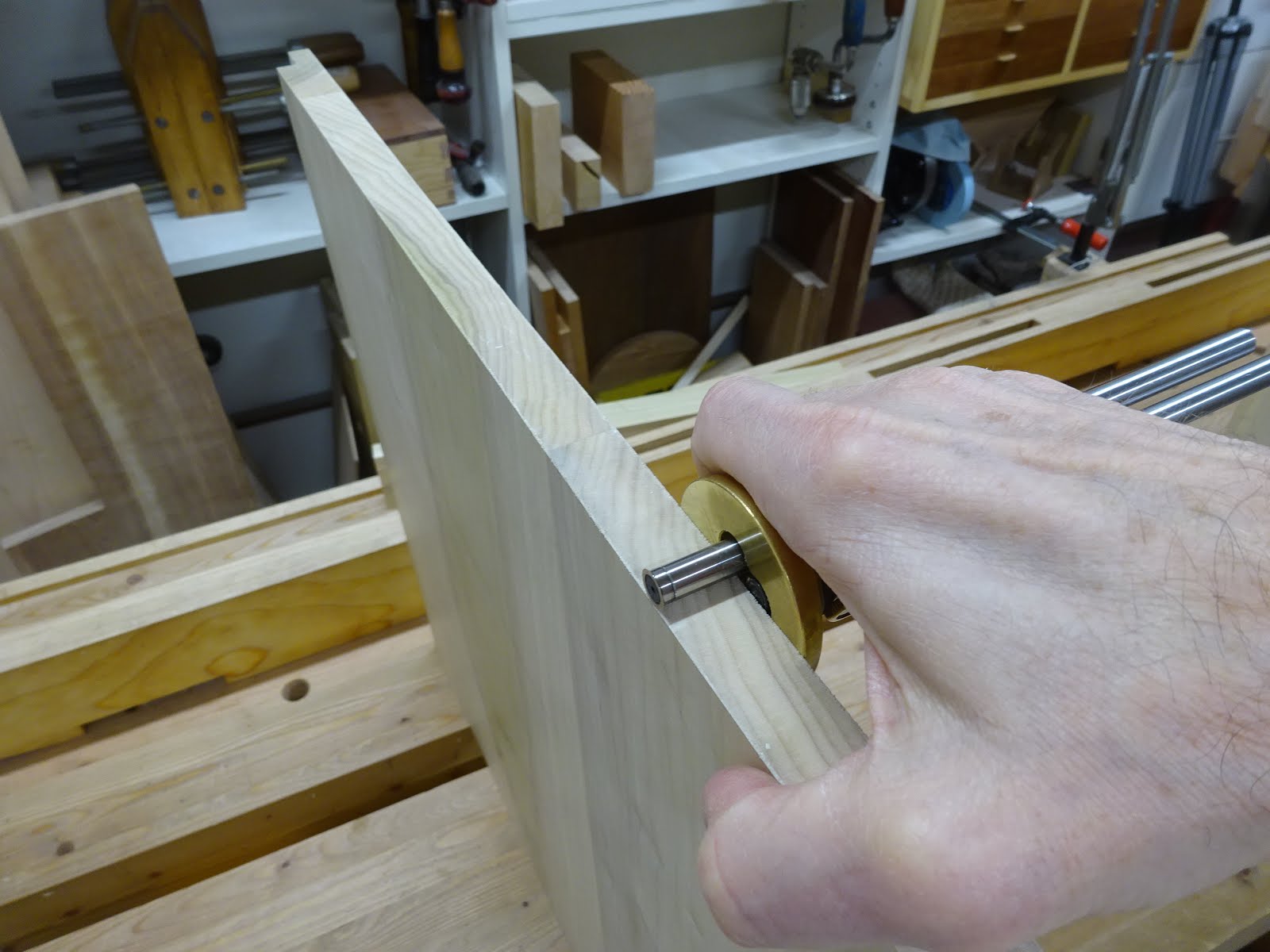
Gauging the baseline on the tail board, referencing off the end
Then I got down to sawing.
Clamped the board creatively and sawed to the lines
Used a coping saw to remove most of the waste
After chiseling to the baseline, I realized I forgot to use the trick that Schwarz wrote about in "The Joiner and Cabinetmaker".  So I added the approximately 1/64" rabbet to the inside face of the tails using a router plane after they had been cut.  For the second tail board I made this rabbet ahead of the cutting.
Pencil points to the shoulder of the shallow rabbet
The tiny rabbet makes it easier to transfer the shape of the tails to the pin board.  It worked fantastically well.
Tail board resting on the pin board, ready for marking the pin board
The case bottom (the pin board) had cupped a little, so in the picture above you can see that I've clamped a straight piece of wood to it.  After that, the tail board fit nicely on the pin board with no gaps showing.

I didn't get any pics of working on the pin board, but I was very careful to cut straight and the long row of tails fit into their sockets with only a few rounds of trimming and fitting.
First corner done
Following is a close-up of the right corner in the above picture.  That's the rear of the cabinet where the rabbets are.  I had included one "straight" dovetail the width of the rabbet.  Because of the rabbet, the tail piece is only 3/8" thick there.  So I only removed half the material as I did for the other dovetail sockets so that the straight tail would fit right.  This was a great solution for keeping the rabbets invisible from the outside.
Close-up of the right-most dovetails
After dovetailing the second bottom corner, I worked on the upper joinery.  For this cabinet, the sides are joined at the top by three rails using half-blind dovetails.  And here's where I made an error that I hope doesn't come back to haunt me.  I'll get to it at the end of this post.
Used the baseline of the pin board to mark the shoulders of the top rails
Created the 1/64" rabbet on the inside of the uncut tails
After cutting the tails, transferring the shape to the upper edge of the side
Carefully sawed and chiseled the recess
All 6 joints fit very nicely
Right side with three blind dovetail sockets
And the first test-fit of the main carcase
So here's where I went wrong.  This design is odd in that the lower edges of the sides are dovetailed, but the upper edges of the sides have dovetail sockets (aka, they are pin boards).  Because of the 1/64" rabbets cut on the inside face of the tail boards, the sides will overlap the (carcase bottom) pin board shoulders by 1/64".  When assembled, that makes the distance at the bottom between sides  1/32" less than the distance between the bottom board shoulders.  But I marked the top rail shoulders from the bottom board shoulders - I should have assembled the bottom with the sides and marked the top rail shoulders from the inside dimension of the sides at the bottom.  As it is, when dry-assembled, the width is more than 1/32" greater at the top than at the bottom.

I'm hoping that I can live with this.  I know how important it is to have a perfectly square carcase.  This is going to make it challenging to get the length of the mid-rails right.  But assuming I get them right, I think this discrepancy will have minimal effect on drawer fitting.

Next up: dadoes for the drawer dividers.