Showing posts with label Sharpening. Show all posts

Thursday, May 30, 2024

Centre Bits

At a recent show of the PAST Tool Collectors, I bought several centre bits.  I'd been curious about these for a long time and wanted to see what they're about.  And the price was right - 12 bits for $12!

Before anybody gets all worked up, I'm using the British spelling of "centre" just because it's how I've seen it written most of the time.  And because it makes me giddy.  I don't know this for sure, but I suspect that these bits were not used as much in America as they were in England.  Please correct me if you know otherwise.

The line-up of centre bits.

Note that the holes that these bits cut are not (or are no longer) standard sizes.  I wonder if they ever were.  The sizes (in 16ths) and makers (with all markings) are, from left to right:

  • 4 1/2 / 16     No markings
  • 5 / 16           No markings
  • 6.5 / 16        R.M. DIXON / HERMITAGE WORKS / SHEFFIELD
  • 9+ / 16        W. CHANCE & SON
  • 9.5 / 16        T.E. WELLS & CO. / CAST STEEL
  • 13.5 / 16      E. COOPER / IRONMONGER / CHESTER
  • 15.5 / 16      No markings
  • 15.5 / 16      W. MARPLES & SONS (with flower? or clover? logo)
  • 18 / 16         R.M. DIXON / HERMITAGE WORKS / SHEFFIELD
  • 19 / 16         J. ASKHAM (this may be an owner's mark)
  • 20+ / 16       No maker mark, but "AR" and "1 1/8" possibly stamped by owner
  • 21 / 16         T.E. WELLS & CO. / CAST STEEL

In his writing for "The Woodworker", Charles Hayward notes that these bits are best suited for shallow holes.  Especially when boring into end grain, the center point can follow the workpiece's grain, leading to a curved or crooked hole.  That problem was solved when spiral auger bits came around, as once the perimeter of the spiral section enters the hole, it keeps the bit from wandering.

Shannon Rogers did a nice video on centre bits that tells a more complete story, but I'll mention a few things here.  First, lets talk geometry.  The following pic shows a typical bit.

Cutting lip at left, center point, and spur at right

For these bits to work properly, the cutting spur has to be longer (closer to the wood) than the cutting lip is so that it scores the wood before the cutting lip starts removing the bulk of the waste.  In this picture, the spur is up to a line on the paper, but the lip is a few millimeters lower.

This pic shows a bit with cutting lip equal to the spur.
This bit will not cut a clean hole as is, so I had to file the lip down a bit.

Here, you can see the spur has scored the perimeter of the hole.

As the bit goes deeper, the cutting lip engages to remove the waste.

Sometimes you get a nice spiral shaving

It's easy to sharpen these bits, but it's also easy to sharpen these bits incorrectly.  It seems like most bits in the wild had not been sharpened properly at some point in their lives.  Lets start with the cutting lip.

The following picture shows a cutting lip from the side.  There is quite an angle on the underside of the lip (top side in the orientation shown).  This clearance angle assures that the leading edge of the lip is what cuts the wood.  Many centre bits are sharpened incorrectly by filing the underside in such a way that the leading edge can't cut the wood.  If you were to file in the direction my fingers are pointing, you might get a sharp edge, but you would also create a new bevel on the underside and the heel of that bevel would contact the wood before the cutting edge can, rendering the bit useless.  One should only file the top side of the lip, with only slight work on the underside to remove a burr.

Note the angle on the cutting lip

The correct thing to do is to file the top of the lip.

Red marker on the top of the lip will help gauge progress

Red marker removed, feel for burr on underside, 
remove the burr and the lip is sharp

Now take a look at the center point.  It is actually a three sided awl, with each corner a cutting edge.

In this close-up, you can see two facets of the center point

In Shannon's post about these bits, Bob Rozieski commented that when these center points are not sharpened evenly on all facets, you can change the diameter of the hole that the bit cuts.  If you think about it, it's the lateral distance between the center point and the cutting spur that determines the hole diameter.  Some of mine were cutting holes pretty far off of standard sizes.  I'll have to take a look at the center points to see if anything more can be done to get them dialed in to cut proper diameters.

Here is a picture of the other side of a bit, showing the third facet of the center point.

This third facet started out  in plane with the rest of the back of the bit

I noticed that on most, if not all of my bits, this back facet is slightly convex along its length.  That probably puts the very point more in line with the central axis through the bulk of the bit.  My thinking is that would result in a truer hole.

The last part to sharpen is the cutting spur, seen at left in the previous picture.  Its leading edge is towards us in the picture, and its top point needs to be filed to a sharp cutting geometry, without reducing its length.  Too many bits have been ruined by sharpening the spur poorly.  Never file the outside of the spur, as that will change the diameter that the bit cuts.  Only file the inside concave curved area, but be careful not to go so far as to reduce the length of the spur.  Small round files or sandpaper wrapped around a round (cylindrical) object work well for this.

One thing I'm not sure about is an aspect of the cutting lip.  Shannon reports that the outside of the lip starts cutting before the inside does, thereby creating a slightly domed surface in the hole you're cutting.  The bits I have are all over the map on this point.

Note the difference in angles of the cutting lips.

The bit at left would cut as Shannon states, with the outside of the lip cutting first.  But the bit at the  right would have the whole lip cutting at the same time, leaving a flat bottom.  Did different manufacturers make them with different geometries?  I don't know.  Did they all start out looking like the one on the left and then some get filed improperly to look like the one on the right?  I don't know.

That ends my treatise on centre bits.  I don't know if I'll pick them up instead of my auger bits.  But if I need a shallow hole and don't have to get an exact diameter, these might just be the ticket.  I'll end with pictures of the maker stamps.

T. E. Wells

R. M. Dixon

W. Chance & Son

(Wm?) Marples & Sons
Looks like an owner once filed a waist in the shank, maybe to fit their brace chuck

E. Cooper


Sunday, December 4, 2022

Two Very Interesting Portable Saw Vises, Part 2: Atkins

Part 1 showed the workings of an E. C. Stearns portable saw filing vise.  Today I have one by E. C. Atkins.  This one was more difficult to figure out how it worked, but I was able to find the original patent and it helped to read it a few times.  The patent, combined with studying and playing with the vise, helped me figure out how it is used.

On the left, is written "E.C. ATKINS & CO. IND'P'L'S"
On the right, "IND. PAT. OCT. 22, 1912"

That ridged area in the middle, uppermost in above photo says "SPRAY", for Charles H. Spray, the inventor and patentee.

More detail of the important parts - will discuss them below

I learned from Bob Demers of the Valley Woodworker blog about Datamp.org, a site that helps people find patents related to old woodworking tools and equipment.  It gets its information from the U.S. Patent and Trademark Office.  Based on the patent date, I found the original patent text and drawing (patent no. 1042049).  My saw vise is a little different from the one pictured in the patent.  I guess they made some modifications after the patent application and approval.

Part A is called the base plate and it has provisions to affix the vise to a piece of wood.  In cross section it's shaped like an "L" so that it can wrap around the corner of a piece of wood.  There's a countersunk hole for a screw in the middle of the leg of the "L".  On the other leg there are also two pikes meant to sink into the piece of wood to hold it steady.

I'm getting ready to drill for this screw

Showing one of the pikes with the indent it made in the wood

I'm pretty sure the flat spot just above the pike was meant to be struck with a hammer
(Note: here I have it mounted to the piece of wood incorrectly - the pikes
should get sunk into a face of the board whereas the screw goes into an edge)

It took me a long time to figure out how this thing is supposed to be used.  I read the patent application and reviewed the drawing many times and it was still a challenge.

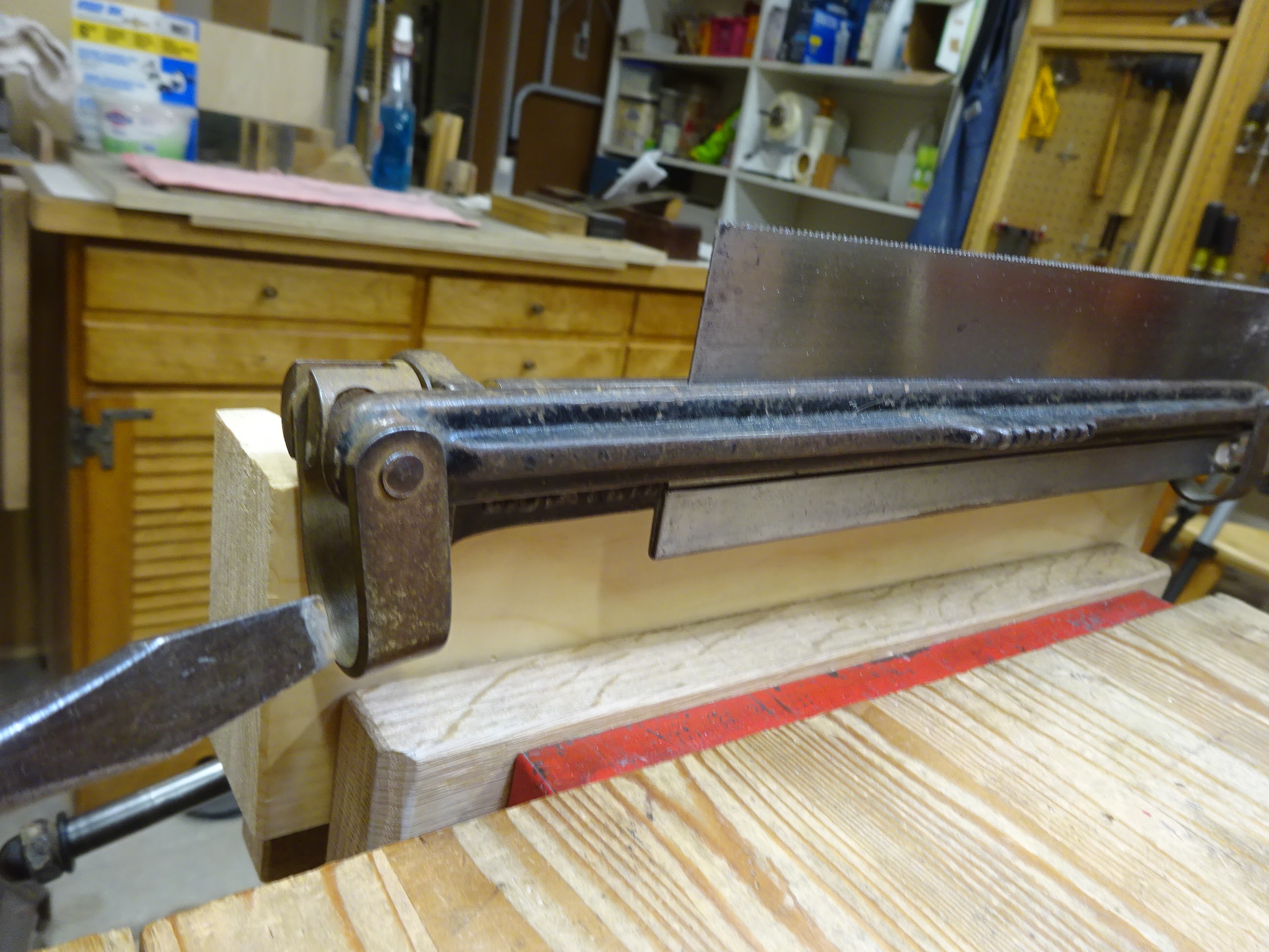
In my second picture above, part B is the moveable clamping bar that swivels using the "universal swivel joints" at each end.  Part C (also called a clamping bar in the patent) is a cylindrical rod that can rotate on its axis, thanks to its smaller turned ends that fit into holes in the base A.  When clamping bar B is rotated, it comes into contact with bar C and the two bars make up the clamping jaws.  The two arches (D) are springs that put pressure between B and C.  Here's how you set it up.

Ready to put the saw in the vise.
Bar B is in its relaxed position - note position of arches D.

Insert the saw so the teeth just protrude between B and C

Then rotate bar B so it clamps the saw against bar C
(View from other direction)

Now note the position of arches D

And here's a closer picture of the saw clamped between B (behind saw) and C (foreground)

And here I am filing that small gents saw - works nice!

Here's a side view of how the swivel works and clamps a saw plate.

Cylindrical bar C is at left, bar B uppermost, D spring arches to right

In clamping position, B rotates left and down, against C, D arches are up

The patent also said that the arches D can be used in another way to allow jointing and setting the saw teeth.  They can swivel to the downward position shown below so that the tooth line can be raised farther above the clamping jaws.

Saw vise with arches D in jointing/setting position
(screwdriver tip (at left) is pointing to the arch D)

Holding a file as if I was going to joint the teeth.

I'm not sure with this small saw if there would be enough room to set the teeth, but that's not critical.  One last thing: there is supposed to be a piece connected near the screw (the screw that secures the vise to a board) that swings out and helps secure the vise to a board.  This example doesn't have that "dog", as it's called in the patent.

So that's it.  A very interesting tool, to be sure.  I didn't even know these existed, and now I have two.  I might be getting rid of one, though - have to see about that.

Friday, December 2, 2022

Two Very Interesting Portable Saw Vises, Part 1: Stearns

Along with the other tools that I recently bought in an auction lot were these two items that I'd never run across before - never knew such a thing existed.  They're two "jobsite" saw vises, made to be compact enough to carry in a toolkit.  I'm certain they're intended to attach to a saw horse for jobsite sharpening of saws.

The first is by E. C. Stearns.  It's got a screw clamp to attach it to a piece of wood for stability and the clamp swivels out of the way for compact stowage.  The vise clamps a saw in its jaws using a cam mechanism.

E. C. Stearns no. 500 saw vise

Stamped name shows up great after some cleanup

No. 500

Underside shows the swiveling arm with clamping screw

End view of the vise shows the clamping screw in clamping position

Here it is clamped onto a 2x4 that is held in my bench vise

Top view.  I'm holding the cam lever.  Yellow arrows show slots allowing part A to slide
when cam lever is moved to right to squeeze against part B.
Green arrow shows the gap between parts A and B when cam lever is to left.

When lever is moved to right, A is pressed against B and the gap is gone

Here it is clamping a 12" gents saw

And a closer shot

And it works pretty well!  Shown here is an inverted "L" shaped wood piece that the vise
is clamped to; the "L" block clamps in my end vise to raise the work up to better level.

One last thing about this saw vise.  Part A has a hollow area up where it clamps to part B.  And in that hollow is a length of braided steel wire whose diameter (approx. 1/4") is slightly greater than the depth of the hollow.  My guess is that the braided wire has some compressibility and gives a better hold on the whole length of the saw plate.

Dental tool (left) is lifting the braided wire out from where yellow arrow points

This shows how the wire is attached: it's simply stuffed through a hole in each end!

And here's the only problem.  The wire is not taut enough to stay in place in its groove.  I have to be very careful that it's in the groove when clamping a saw plate - otherwise I clamp a big bend in a saw plate.  When researching this, I read that someone replaced the wire with some rubber screening spline (or something similar).  That's an option, but I'm not sure if I want to replace an original part.

This is getting long, so I'll write about the second saw vise in another post.  Until then ...

Thursday, November 4, 2021

Expansive Auger Bits, Part 2

Last time I discussed how expansive bits work and showed the sharpening of the Irwin #2.  Today's post will cover the Clark Expansive bit from T&L Co., New York.  BTW, I could find zero information on T&L Co.  My guess is that they were a hardware store or distributer who put their own name on a tool made by a bigger name company.

The markings on the tool

This one was found with only the small cutter

When tightened, there is a good size gap where I'm pointing

This bit (left) compared to the Irwin #2

This Clark expansive bit is made differently from the Irwin.  The clamp (lower left) is a separate piece, and tightens the adjustable arm into the dovetailed "way" when a screw is tightened.  On the Irwin #2, a slot is machined in the body of the bit and the screw has to bend the metal to force the adjustable arm into the dovetailed way.

Notice the difference on these two bits where the adjustable arm dovetails into the main body.  With the Irwin #2, the adjustable arm just fits much better into the dovetailed way.  With the T&L Co. bit, there is some slop, and this leads to a large gap (about 1/32") between the radial cutter of the adjustable arm and the main body.

I sharpened the adjustable arm's radial cutter and spur like I did on the Irwin #2.

Used a dowel wrapped in 220, then 600 grit sandpaper to work on this concave area.
You can see at the cutting edge where a previous owner cut a much more severe angle at that edge.

Used a very fine file and extra fine diamond paddle to dress the front edge of the spur.
Also removed the burr from the outside with VERY light passes of the diamond paddle.

Then I got to the cutters on the main body.  This one differs from the Irwin #2 in that it has a spur on the main body.  In effect, it could be used to cut a 7/8" diameter hole by removing the adjustable arm and boring with the main body of the tool.

Radial cutter (red arrow) and spur (yellow arrow).
The radial cutter was very dull and needed files and diamond paddle to get it sharp.
Note the "escapement" for chips to go after being severed from the wood.

Look at the shape of the spur.  Clearly it has been sharpened too much or very badly.
I went very carefully to sharpen it without losing any more height.
Note how this radial cutter and spur are cantilevered out from the base of the lead screw.

Before I did anything with the dovetailed ways to reduce or eliminate the gap, I tried out the tool on a 2x4.  It cut very nicely and left clean walls on the (approx. 1 5/16") hole.

Red arrow: adjustable arm's spur cutting the circumference.  Radial cutter not yet cutting.
Green arrow: main body spur cutting a 7/8" circumference
Yellow arrow: a thick chip coming through the main body radial cutter escapement

OK, so here's what I'm discovering.  The thick chip in the above photo is coming towards the camera.  It is coming through the main body escapement and doesn't even get near the gap (clearly seen just below the chip in this photo) between the adjustable arm and the main body.  So it doesn't get clogged in that gap.  I bored a couple of holes with this bit and didn't get any clogs.

Smooth walls on both long and short grain

Here's a chip that came off one of the radial cutters - not sure which one

Here's the only chip that got caught and it was inconsequential

While this bit cut nicely, the hole got a little larger at the exit than at the entry.  So, just like with the Irwin #2, the adjustable arm slipped a little.

Just wanted to add a little more about chip clogging.  I noticed a big difference in the position of the main body radial cutter between the Irwin #2 and the T&L Co. bits.  Look at these pics, both of which have the adjustable arms in the same orientation.

Irwin #2 main body radial cutter

T&L Co. main body radial cutter

The Irwin #2 main body radial cutter forces chips into the location where, if there was a gap, they would get caught.  As we saw a few pictures ago, the T&L Co. bit expels chips away from the seam between adjustable arm and main body.

This Irwin #2 radial cutter forces chips down towards the seam between the
adjustable arm and the main body.  There is no gap, so all is safe.

I don't know about you, but I find this fascinating.  I wonder if the manufacturer of the T&L Co. bit knew something that Irwin didn't.