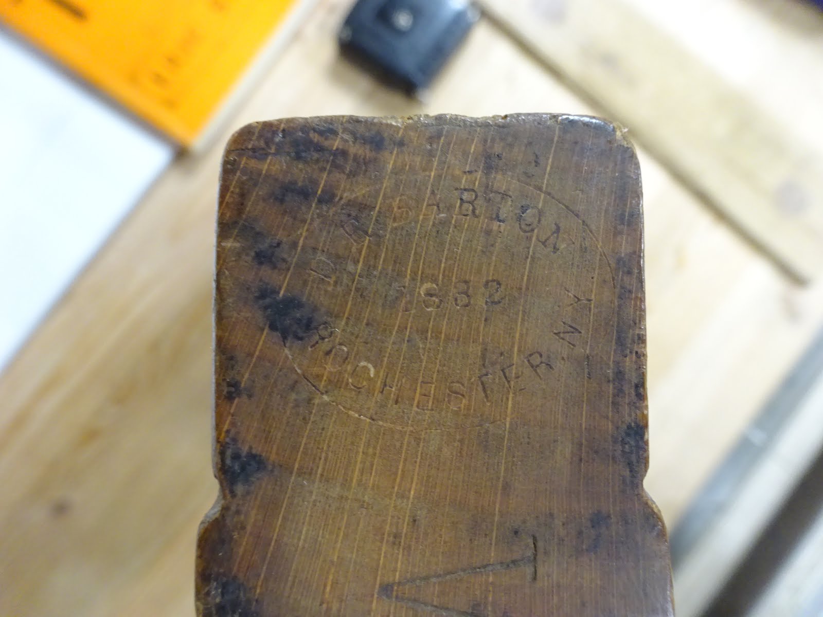
The D.R. Barton rabbet plane that I recently picked up was in need of a bit of work if it was to become a user once again.
 |
| D.R. Barton 1 1/2" skewed rabbet from the 1870's |
The sole had been planed by a prior owner, but it wasn't flat and was slightly twisted.
 |
| The sole, as found. Winding sticks would show slight twist. |
I planed the twist out and got the sole flat. The right side of the plane wasn't even close to flat and also had a bit of twist. It also wasn't square to the sole. I planed a bit off the right side, but still had a problem where it meets the sole.
 |
| The right side of the plane, forward of the mouth is rounded at the sole |
 |
| Right side of the plane, to the rear of the mouth |
I had hoped not to plane too much off the sides, but the corner where the right side meets the sole needs to be very crisp. Forward of the mouth, this area was quite rounded and that made it necessary to remove almost 1/8" of material.
When the right side was flat and square to the sole, with a crisp corner, I had to decide what to do about the left side. It's not as important for that side to be square to the sole, so I could have left it as found. I decided to make what was (probably) originally a 1 1/2" rabbet plane into a 1 1/4" rabbet plane.
 |
| Scribed a line 1 1/4" from the right side |
Planing to this thickness gave me a flaw-free body, for the most part. I was also able to keep the entire original maker's stamp on the front end.
 |
| The plane is now a bit thinner than in this picture, but I still have the whole maker's mark |
As long as I was obliterating most of this plane's patina, I planed the top to be flat and square to the rest. Then I added back in the upper edge rounding / chamfering.
 |
| Upper edges marked for the chamfers and rounding |
The wedge and iron were next. Because I made the plane body thinner, I needed to file the sides of the iron to get it to match the body.
 |
| Filing the right side of the iron |
The key is to file so that you can center the tang in the mortise and have the right side and cutting edge of the iron matching up closely with the plane body. BTW, the side of the iron needs to be filed at an angle such that the back edge doesn't extend out from the body.
 |
| Front of plane to right: note how rear aspect of iron recedes into the plane body |
Finally, I filed the left side of the iron so that it was just a hair wider than the plane body.
I had a little piece of beech for a new wedge, but because all I had was a very small piece I made a prototype from oak first. I wanted to see how difficult it would be to plane the proper angles. Turns out, it wasn't that hard at all.
 |
| The original wedge was pretty beat up |
 |
| Beech, oak and original wedges |
 |
| Oak prototype fitting nicely at front of mortise |
After making sure the beech wedge fit well at top and bottom of the mortise, I added a ramp detail to start the deflection of shavings.
 |
| Ramp at bottom of wedge |
I took a lot of time to try to make the iron fit the bed, and it's still not quite right. I may end up putting a thin piece of leather behind the iron, a trick I once read about that woodworkers of old used when an iron didn't bed properly.
 |
| Trying to get light where I needed it to work on the bed |
 |
Taped wax paper to the sole to filter the light and
Using a straight-edge to see the gaps |
The bed doesn't really need to be perfectly flat. But the portion that supports the base of the bevel should mate well.
 |
| It's probably OK to have that gap, as long as the whole of the iron just behind the bevel is supported |
 |
| With wedge and iron installed, there's about 0.005" gap (but less than 0.002" at the base of bevel) |
To get the bed to mate with the iron better, I used the candle soot trick that I learned from Bob Rozaieski.
 |
| Hold bevel side just above a candle flame, but not long enough to heat it |
 |
| This will leave candle soot |
 |
| Put it in the plane, tighten the wedge and tap the back of the iron to advance it a few millimeters |
 |
| The areas where the soot is rubbed off show where the contact with the bed was. |
 |
| You can also see the soot remaining on the bed |
From there it's a matter of scraping the sooty areas off the bed to try to level it to the iron. This takes a LOT of patience, with repeated sooting and scraping. And I still didn't get it perfect, though the plane works OK now.
After this was all done, I coated with BLO on three successive days, wiping off the excess each time after about 15-20 minutes, then left it several days to dry.
 |
| The finish |
 |
| Picture of the beautiful and distinctive figure of quartersawn beech |
 |
| And thar she is, all gussied up, ready for another 140 years of work |
In use, the skewed iron pulls the tool into the work as you plane. I've got a bit of learning to do before I get used to that and have it working for me like it should. Maybe it's better to use a straight iron for most of the work, then use the skewed iron for the last shaving or two to smooth out the bottom of the rabbet.