Friday, May 25, 2018

Make a Beading Plane

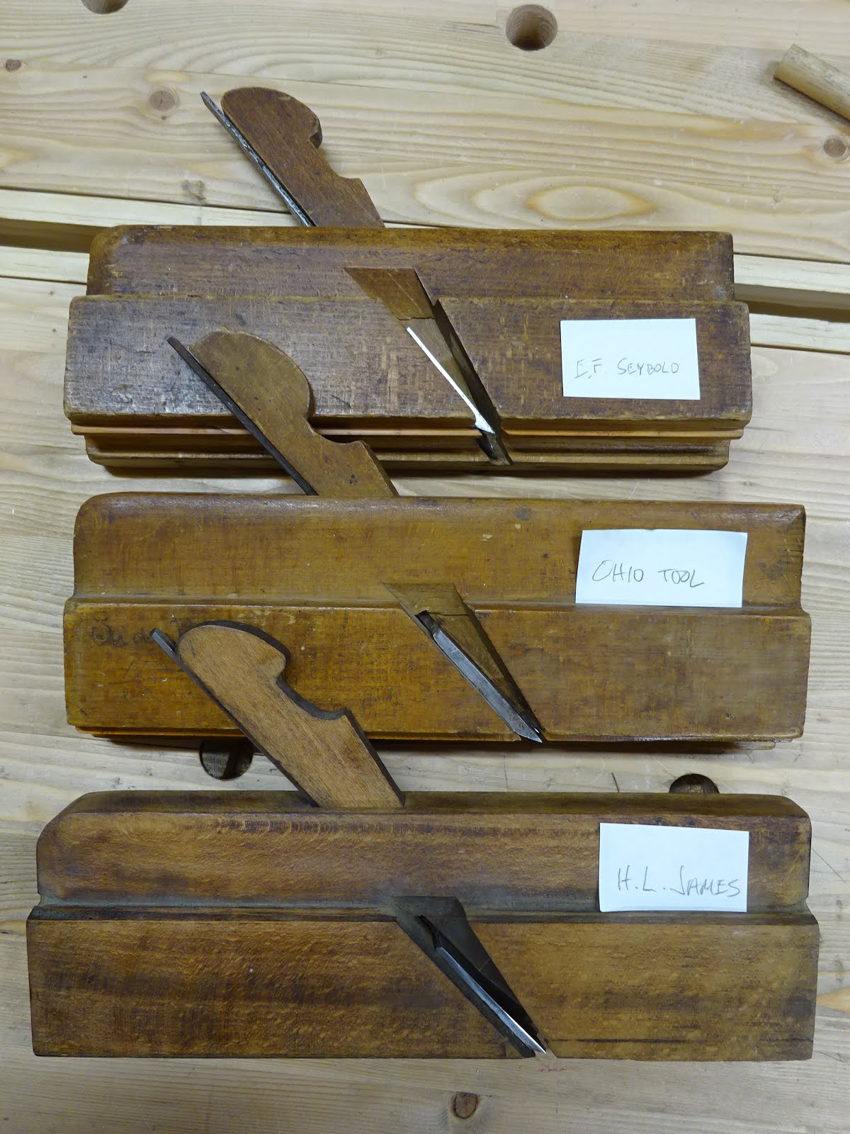
After all the time I spent comparing the three half inch beaders and then refurbishing the Ohio Tool plane, I got to thinking about whether or not I could make my own beading plane.  So I used the information I got from the three beading planes and made a drawing in Sketchup.
Sketchup model
Alternate view
Some critical dimensions of the sole:
Sole dimensions
As with the last post I didn't take any progress pics, so all these are after the fact photos.  I started by making a mock-up of the plane body from a piece of a very old 2x8 with excellent grain.
Pine mock-up
The bed angle is 50° and the breast angle is 62°.  After cutting the rabbet for the handhold, I sawed to the 50° and 62° lines with the help of a square block of wood to guide my saw and removed what waste I could.  I got that technique from an article Salko Safic wrote in Issue 3 of his "Lost Scrolls of Handwork" magazine.
Sawing to the bed and breast lines
For the mortise, I drilled a couple of holes before chiseling out the waste and tuning it with sandpaper paddles.  The sole profile was shaped similarly to the way I reshaped the Ohio Tool plane.  Except I used a grooving plane to remove as much waste as I could, then scraped the profile later.
View from the back end showing layout lines
Closer view of the sole at the heel
This came out so good it made me wish I had made a wedge and iron to see if a pine plane would work.

For the "real" plane I used poplar for the upper 90% of the body and maple for the sole.  It's not boxwood, but the maple is pretty hard and should last a while.  Both woods were in quartersawn configuration.
Rear view showing grain configuration and overall shape
Per my plan, the left side (blind) wall is 3/8" thick.  This helped when chiseling the left wall of the mortise, as I could use a 3/8" setup block to rest the chisel on to ensure I pared right to the line.
Paring the mortise wall with help from setup block
Set of brass setup blocks - these things really come in handy
I smoothed the inside of the mortise using makeshift "floats".
* Not made by Lie-Nielsen

Shaping the sole started with careful layout.
I left the layout lines on the completed plane
This next pic helps show the dimensions of the layout.
1 1/4" total width, 1/4" wide depth stop, 1/16" quirk, 7/16" wide bead, 1/2" thick fence
I first used a grooving plane to get close to the bead lines.  Then used the scraping jig that I showed in the last blog entry to get the final shape.  This needed a LOT of patience and took a while.  I also made a 3/8" thick sanding block with 3/8" diameter round-over on one edge.  The 3/8" thickness plus two thicknesses of sandpaper is still a little shy of the 7/16" bead diameter.  This gave a little wiggle room and helped ensure I didn't sand away parts that I didn't want to sand away.
Sanding block

Block in use smoothing the bead profile
Later, a shoulder plane was used to shape the quirk and depth stop.

I cut the iron from a piece of 1/8" thick O-1 steel and shaped it with files.  I later heat-treated it with a torch, quenched in oil and tempered in the oven.
Hacksawed the iron from bar stock
The wedge was made from a piece of beech and that came out nice.
Body, iron and wedge - how much simpler can it get?
I don't have a "maker's mark", but if I did it might look like this.
The poplar made it easy to stamp this into the body
Well, the proof is in the pudding.  I tested the plane in some scrap poplar and it cuts beautifully!
Test cut
Here's the funny thing about all this.  I have three very old 1/2" side bead planes that I'll probably never use for the furniture work I want to do.  So what do I do?  I make another 1/2" side bead plane!  Not certain why - I just wanted to see if I could do it.  This is a real confidence booster.  I've gotten to a point where I'm confident that if I lay out appropriately, I can saw, chisel and plane to those layout lines.  Just take it slow and I'm sure most of you could do this too, if you haven't already.

Friday, May 18, 2018

Tool Rehab: Ohio Tool 1/2" Side Bead

In the previous post, I compared three 1/2" beading planes.  The Ohio Tool plane was in the best condition of the three and that was why I chose to work on it.  The following pictures are all after the fact - I didn't take any pics while doing the work.
Ohio Tool plane parts
The boxing was glued in well, so I didn't have to remove it and glue it back in.  It was mangled a bit at the front of the plane, but I planed most of that down when working on the sole.

The first thing I do is to re-establish two reference surfaces: the left side and the fence portion of the sole.
Left side of plane (OK, it on the right in this picture, but it's the left side of the plane) needed some flattening
Planed the fence portion of the sole flat and square to the left side
Then I marked a line on the ends that would be the peak of the bead.  I made this line by first setting a wheel-type marking gauge to 7/16" and made a mark referencing off the sole.  Then I used a square referencing off the left side to continue this line across the end.
Gauge line on end
To work on the bead portion of the sole, I made the jig that Bill Anderson shows in this article on the Wood and Shop website.  The jig is simple genius and works very well, though it does take a lot of patience to get to the final shape.  A big thank you to Joshua Farnsworth and Bill for making the article available online.  Man, I'd love to take a class with Bill some day.
Plane body in the cradle portion of  Bill Anderson's jig
Another view - fence sole is flush with top of jig
The adjustable scraper holder part of Bill's jig
You can see from this picture how the jig works
There are some important things about this jig.  First, the two vertical pieces of the cradle should be identical in height and should be flat and straight on top and bottom.  Otherwise, the scraper holder might not run true when scraping the sole.

Also, I made the scraper piece longer than needed.  It's 3/4" wide and about 2 1/2" long.  I purposely didn't make the 7/16" diameter rounded end centered in the 3/4" width.  It is flush with one side of the piece.  This helps me make certain the scraper is aligned properly.  I can hold a small square to the part of the scraper sticking up above the holder, referencing on the holder to ensure the scraper is square.
Close-up of scraper and holder showing surfaces square to each other
After scraping down to the 7/16" line I marked earlier, I planed the tip of the boxing using a shoulder plane.
Planing down the boxing
Then I worked on the side of the boxing and the depth stop with the same plane.
Planing the side of the boxing
The tricky thing about these last two pictures is knowing when to stop.  The gauge line I marked earlier shows where to stop for the depth stop.  (Actually, you should plane the depth stop an extra shaving or two so that the workpiece you're beading won't have a small flat on top of the bead.)  For the side of the boxing (above pic), I gauged a vertical line referencing off the left side.  I've just planed the line away in the end pic earlier in this post.

The iron was in tough shape.  I spent a lot of time flattening the back.
Back side flattened
I also spent a lot of time getting the bevel side shaped right.  Maybe I'm getting a bit better at this, but it didn't seem too tough this time.  It takes a LOT of patience.  I used round chainsaw files at 25° to get the shape close.  Then I honed with fine sandpaper on a dowel at 30°.
Bevel side filed and honed
Tough to get a decent pic of this, but finally got a good match between iron and sole
Test cut in some scrap
This plane cuts very well now - I'm really happy about how it turned out.  I may never have a need for a half inch bead, but if I do I'll be ready!

Friday, May 11, 2018

A Tale of Three 1/2" Beading Planes

I  don't have many moulding planes, but somehow I have three 1/2" side bead planes.  And the funny thing is that I may never need a 1/2" beader with the work I do!

None of these planes is in decent working condition and I wanted to figure out which of the three to put my time into.
Left: E. F. Seybold, center: Ohio Tool Co., right: H. L. James
(all pics below will have same orientation: Seybold on left ...)
The Seybold (Cincinnati) and James (Williamsburg, MA) planes are likely from the 1850 time frame, but the Ohio Tool (Columbus, OH) plane is probably a bit newer.  I had started working on the Seybold, but there are some serious problems that I didn't think were surmountable with my current skill level.  Maybe nobody could.  I might get into details later.

Here are some numbers about these planes.  A minus sign (-) or plus sign (+) after a number means just shy of, or just greater than the dimension given.  I thought it was interesting that there is very little that is standard from company to company in making the planes.

Characteristic E. F. Seybold Ohio Tool Co. H. L. James
Overall Length 9  9/32" 9  9/16" 9  11/16"
Body Thickness 1  1/2"- 1  1/4"- 1  1/4"-
Body Height 3  3/8" 3  7/16" 3  5/16"
Bed Angle 53° 48° 49°
Breast Angle 65° 60° 58°
Left Wall to Mortise (Top) 3/8" 3/8"- 5/16"
Left Wall to Mortise (Sole) 3/8" 5/16" 1/4"
Width of Bead Plus Quirk 1/2"+ 1/2"- 1/2"
Bead diameter (at Heal) 7/16" 15/32" 7/16"
Wedge Thickness 3/8" 5/16" 3/8"-
Iron Thickness at Edge .148" .183" .129"
Iron Thickness Before Tang .124" .157" .103"
Iron Thickness at Back of Tang .076" .103" .086"
Iron Width at Edge 3/4" 5/8"- 5/8"
Boxing Width 5/32" 3/32" 4/32" (1/8")
Boxing Depth 1/2" 5/8" 5/8"
Boxing Type Angled Straight Straight

Here are the soles showing the mouth area.
Thick "blind side" wall on the Seybold
The Seybold has a 3/8" thick "blind side" (left side) wall.  This is close to the same as for the Ohio Tool plane, but look at the difference in width of the "hidden" part of the iron.  That's the part of the iron embedded in the left side of the plane with no exposed edge.  I don't know why there would need to be so much iron not doing any cutting, but the Seybold has about 3/16" there.
Look how much wider the Seybold iron is on the left side
Speaking of the irons, the stats above showed the Ohio Tool iron is quite a bit beefier than the others. Of course, I have no way of knowing if these are original irons - there are no markings on any of them.  Take a look at this side view.
Seybold, Ohio Tool, James
Here's one really interesting thing about the Ohio Tool plane.  Look at the wedge and the shape of the mortise.
Ohio Tool plane (center) wedge has an angled front edge
The others have mortise and wedge with rectangular cross-sections
I've never seen anything like this before.  And I think I really like the design.  As the wedge tightens with the iron, the wedge is forced against the left mortise wall which will help prevent shavings from getting stuck at the spear-point bottom of the wedge.

Now look at this next feature of the Ohio Tool plane.  The part of the breast (front-most part of the mortise) that is not involved with holding the wedge is angled forward.  That is, it is not 90° from the right side of the plane.

Pointing to the part of the breast angle that is angled forward
Added a red line showing relieved angle at outside of breast,
green line shows different angle used at inner part of breast
OK, that was tough putting into words and the pictures don't do it justice.  But hopefully some of you will get the idea.

Here's another interesting thing.  Some planes have angled boxing and others straight.  I'm not certain if there is an advantage either way.
Seybold boxing is angled, others are vertical
The wedges of Seybold and James are very similar with the Ohio Tool wedge having an unusual shape at top (bottom in the picture).
I don't like the shape of the Ohio Tool wedge (middle)
I completely understand having different shapes for the wedges - that can be like a signature.  But I'm still surprised about the many differences in dimensions between these three planes.
Three stooges
Well, there you have it.  After looking at these, I think I'll have the best luck trying to get the Ohio Tool plane back into service.  Not that I have much need for a half inch beading plane ...

Friday, May 4, 2018

Spoon From a Chair Spindle

Some people have the ability to look at a piece of wood and imaging what can be made from it.  I'm not usually one of those people.  But a few months ago I saved a chair from going in a landfill - I mainly wanted the wooden seat for a project - and saw something else useful.
Three of the spindles from the chair's back
Not certain if "spindles" is the correct term for these, but they had a nice curvature to them and I thought spoons could be made from them.  So I gave it a try.
Shows where the spoon blank came from
I used an existing wooden kitchen spoon to mark out the shape and started cutting, gouging, scraping and sanding.
The spoon with another "blank" below it
I worked on the bowl for a long time until I was happy with the thinness.  I've only made one spoon before and its bowl was far too bulky.
Thar' she blows!
I slopped a couple coats of mineral oil on it for a finish.  We've already used it several times in the kitchen and it feels good in the hand. Take that, landfill!