Thursday, December 30, 2021

Nature as Art

While hiking this week in the Big Sur area of CA, came across these interesting pieces of wood.  I've long been amazed at the patterns and shapes you can see in nature.  If the first pic was an inkblot test, what do you see in it?

This one seems fairly obvious

On another downed and weathered log with much of the bark gone, were these patterns.

No Rorschach test on this one - just interesting whorls and curves

More interesting patterns

OK, now I'll fess up.  Besides the bunny in the first pic, I also see (at around the bunny's neck and shoulder) a silhouette of Jimi Hendrix playing guitar.  Only, (if he's facing us in the image) he's playing right-handed and we all know Jimi played left-handed!  What would a shrink reading my inkblot test say about that?

Happy New Year, everybody.  Looking forward to lots of woodworking and learning in 2022.

Thursday, December 23, 2021

One Last Holiday Gift

My sister asked if I could make her a box for the small size Kleenex.  So here's a few shots of that process.  The captions tell the story.  The wood I believe to be sapele - it's recycled from a cabinet another hobby woodworker made years ago.

After squaring up and cutting tails in the 5/16" thick resawn stock

Marking the pins

A closer view - please disregard the overcuts on the tail board

Marking the pin baseline from the tail board thickness

First dry fit

After leveling the top and bottom edges of the dry-assembled box, plowed
the 1/8" wide, 5/32" deep grooves and plugged the ends on the pin board.
The excess wood was flushed after the glue dried.

Dry fit with the grooves lining up

Top fitted.  Top is a smidge over 5/16" thick, with rabbets on upper
surface so that the top of the top is just barely above the sides.
The edges that are seen were "pillowed" to smooth the transition.

Glued up and shellac drying - 4 or 5 coats were used.
A coat of paste wax finished it up.

The top can float, but is fairly tight.  I'm happy with the relatively even reveal.

Here it is next to another I made about 10 years ago in the power tool days.

The top of that one was glued on and look what happened over time.

Glamour shot

I'm certain my sister will love this box.  The wood is gorgeous and finished beautifully.

Thursday, December 16, 2021

A Couple More Gift Ideas

It's unlike me to be this crafty, but I had a few ideas this year.  First off, my wife is a swimmer and uses a swim cap in the pool.  Afterwards she soaks it and then hangs it on a shampoo bottle to dry.  I thought I might give her something custom made for that purpose.  Enter the palm tree swim cap rack.

The green paint was an afterthought, but looked good

Here are the five parts.  Post is 9" long.

Bottom of the 3/4" square post has crossed housings into which
fit the half lapped 5/8" tall feet

Same joinery at the top, except the "fronds" are 1 1/8" tall

And here it is, modeling with a swim cap

It's finished with two coats of poly.  I hope it's useful.  Even if she doesn't like it, it makes me happy to have made it.

The second thing I made uses wine bottle corks and small chunks of wood.  She recently mentioned that she didn't have a cap with a good seal on her soda bottles (she only drinks 1/2 to 1/3 of the bottle at a time and they can go flat).  So I thought I'd try to make something.  I got out the bungee lathe and formed a few bottle stopper caps.

Shaping the stoppers

After shaping on the lathe, I cut them off and smoothed over the top of the cap.  I needed to bore a hole in the bottom.  This was interesting, first because I was boring into end grain and second because the parts are small and I needed a good way to hold them.  I ended up making a jig to hold them - a 1 1/2" hole in a 1" thick piece of wood and a saw kerf extending from the end of the piece of wood to the hole.  This kerf allowed a clamp to be used to tighten the jig around the cap.  The diameter of my caps is just under 1 1/2", so a little piece of leather wrapped around the cap, stuffed into the hole in the piece of wood and a clamp to squeeze it tight did the trick.  And boring the 7/8" hole into the end grain was easier than I thought it would be.  Four of these are cherry and one is a mystery wood.

The corks are epoxied into the caps

I finished the wooden caps with several coats of shellac.  Time will tell if that was a good idea.  They might get wet from time to time.  And I don't know they'll seal well enough to keep the sodas from getting flat - we'll see.

Anyway, these were quite fun to make.  I didn't have a definite plan at the start.  It was just good to get in the shop and fool around.

Enjoy the holidays, everybody!

Thursday, December 9, 2021

Christmas Gift Idea: Roubo Phone Stands

I have Ron Aylor to thank for this one.  I was fascinated when I first saw Roy Underhill make the Roubo book stand and ever since have wanted to make one.  Ron's post showed that you can adapt the idea to make smaller versions to use as a phone stand.  You can see how Ron did it in the linked post.  My method is mostly the same.

Prototype version

How it looks with phone

I started with a prototype to learn about any pitfalls so I could make fewer mistakes on the real thing.  One thing had to do with allowance for a power cord.  In the next pic, you see the 3/8" wide slot for a power cord that goes almost back to the knuckle.

Slot for power cord

Two things are important here.  First, the slot should lead to a connection with the knuckle.  In this pic, the shelf that the phone rests on is connected to the 1st, 3rd and 5th knuckles.  If I had laid it out so the 3rd knuckle was attached to the upright portion, there would be virtually no support for the wood at the back of the power cord slot.  Even so, there is very little material connecting that middle knuckle to the front ledge.  And that brings me to the second thing: for future pieces, I made the middle knuckle much wider than the rest.

Side view of the phone stand

Oh, yeah, there was a third thing I learned making this one.  I wanted the knuckles to be round in cross section, like in the picture above.  But when chiseling out the material for the knuckles prior to sawing the blank apart, I couldn't get deep enough.  I don't own any thin paring chisels and my regular bench chisels couldn't get deep enough while keeping the round shape.  On this prototype, I ended up breaking and splitting some wood to get it to open up.

So here's the story on making the real things.

9-10" long x 3 1/4" wide x 3/4-13/16" thick blank.
Lay out the knuckles.  This pic looks like I've laid out 6 knuckles,
but there are only 5 - the middle one is much wider than the rest.

About 3-3 1/2" from the bottom, lay out the knuckles, including the
cross section circle on the edge as a guide.

Knife lines at the base of each knuckle.
Drill 1/16" through holes at each corner.

I don't have a coping saw blade small enough to fit in the 1/16" holes, so I used the trick from Roy's show.  I made a little saw from a hacksaw blade and some scrap wood.  The piece of blade has a pointy end that can get inside the 1/16" holes - just barely.

Cut a section of a hacksaw blade, teeth pointing towards right (pull stroke)

Made a handle and I've got a specialty saw for the job

Put the tip in the hole and yank back, starting a tiny kerf

Getting deeper ...  You can work from both sides.

Eventually the whole blade fits in there and you can continue the cut.
This took a long time, but got easier and quicker with subsequent phone stands.

After the slots were cut, chisel out the knuckles.
Notice they didn't come out very round ...

Re-saw the blank into two, down to the knuckles - both top and bottom

Be careful when separating the book stand - these things can be fragile.
I ended up successfully gluing this one back together.

Saw off the excess to create the shelf and to shorten the front foot
to get the phone stand to sit at the right angle

After this was some clean-up of the sawn surfaces.  I used planes as much as possible, but a scraper did a lot of work.  The feet and the top of the backrest got some decorative shaping.  And to personalize them for the giftees, I added some carving to the backrest.  I'm definitely not a carver, but this was kind of fun.  I used paper templates glued to the backrest to guide marking out the outlines, then removed the paper and did the rest with what carving tools I have.

First two with Celtic knot and heart

I used two coats of BLO as a finish.  Very happy with how these came out.  I just hope the recipients like them.

And here they are all finished up and ready for the giving


Thursday, December 2, 2021

Make a Small Moxon Vise from a 2x4

Having recently made some wooden screws and wanting to put them to use, a Moxon vise was in order.  A chunk of a 2x4 was used for the project.  Two pieces, each approx. 18" long were squared up to about 1 3/8" x 3 1/4".

The parts

After marking for the holes, an expansive bit was used to bore 1 1/4" holes in the front piece.  A standard 1" auger bit was used for the back piece.  The back piece needed inside threads, so a scrap of the same 2x4 was used first to see how it would take threads.  Surprisingly, it took threads very well, so the rear piece of the vise was tapped.

Inside threads in the rear piece

A way to keep the front chop attached to the screws was needed.  The screws were put on the bungee lathe and a 1/4" (strong) notch was excavated between the threads and the location of a handle.  A "keeper" was made from some 1/4" thick stock by boring a centered hole and then splitting the piece in half.

The split keeper next to it's actual location

Showing how the keeper holds the screw to the front chop

The screws needed handles, so a piece of 1/2" dowel was fitted just a little loosely into holes bored in the back end of the screw.  A 1/8" dowel was used at the ends of the 1/2" dowel to keep the handle from falling out of the screw.

Knife points at the small dowels holding the handle to the screw

The vise in action

This thing holds incredibly strongly.  And if leather was added to the chops it would be even better.  Now whether or not this Moxon vise actually gets used is another question.  Time will tell.

Thursday, November 11, 2021

Expansive Auger Bits, Part 3

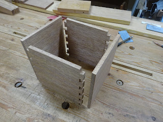
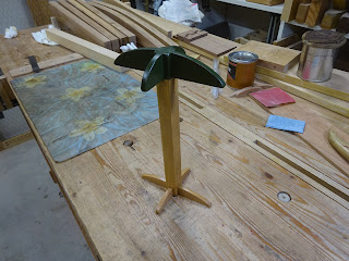
In parts 1 and 2 of this series, the Irwin #2 and Clark Expansive / T&L Co. bits were featured.  This time, it's the Irwin #22.  Its form is very similar to the #2.

Irwin #2 at top, #22 bottom

Unlike for the other two expansive bits, I've got both the long and short cutters for the #22.  The two bits in the above picture have a lot of similarities.  While they were probably made a few decades apart, they have the same thread on the lead screw, the same overall length and the same relative position of the main body's radial cutter.  The main difference is how the adjustable arm is clamped.

The Irwin #22 close up

Irwin #2 top, #22 bottom

The #2 clamps the adjustable arm using a screw (turned from the front) that squeezes together the main body, that has a kerf cut into it, and this in turn pushes the dovetail of the adjustable arm into the dovetailed way of the main body.  The #22 has a very different mechanism.
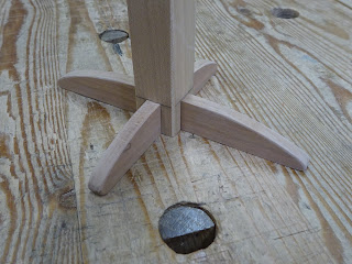
"Wheel" removed

The lower edge of the wheel is in a wedge shape ...

... that matches a wedge shape where it resides in the main body

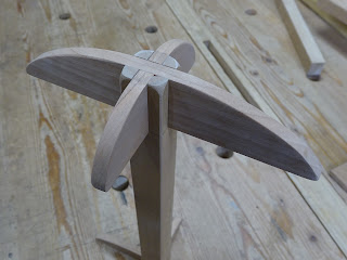
When the screw is tightened (from the back side), the wheel is pulled down into its seat.  The gear teeth on the wheel mesh with the teeth on the adjustable arm.  The toothed edge of the adjustable arm has an angle that matches the wedge angle of the wheel.  As the wheel gets pulled down into its seat, the adjustable arm is forced up into the dovetail way of the main body.

As wheel gets pulled down (red arrow), adjustable arm is
 forced against main body (yellow arrow)

There seems to be poor machining of the mating surfaces of the adjustable arms and the main body.  In the following pics, the long cutter is installed.

Right side showing gaps in the dovetailed ways

Left side showing some gaps at dovetail ways (red arrow), but also
it appears the adjustable arm is making contact with the main body at the yellow arrow,
which does not allow the dovetails to fully seat. 

I've been frustrated at attempts to eliminate the gap between the adjustable arm and the main body.  After spending several hours over the last two days studying it and trying some judicious filing, I can't get the gap to close.

Here is what happens when I use the bit to bore a hole.  I get into the cut several turns, and then things start bogging down.

Using the small arm to bore (approx) 1 1/4" hole.
Shavings clogging the works.

This is what's left when I pull out the bit and remove most of the debris

I can't be certain that this is what starts the bit on the road to poor performance, but that's what I think it is.  I'd love to be able to film the cutting action close-up, but that's far beyond my tech capabilities.

My thinking is that this model is simply a poor design that was poorly machined.  In the next photos, look at how the adjustable arm is supported when making the larger diameters for each arm.

Short arm at minimum diameter setting: wheel contacts arm in center of arm

Short arm at maximum diameter setting: wheel contacts arm only at right end of arm

Long arm at minimum diameter setting (about 1.5"): wheel contacts arm in center of arm

Long arm at maximum diameter setting (about 3"): wheel contacts arm only at right end of arm

An indication of the poor support of the arms when at their max diameter setting is that I can jiggle the short arm when it is fully tightened.  My thought is that with only a small part of the toothed edge of the adjustable cutter being supported, just a little torque can knock these cutters out of whack.

For comparison, here is a picture of the Irwin #2 with long cutter arm in place at maximum diameter setting.  The arm is supported from its right end to where it exits the main body.

Irwin #2 at max diameter: arrows show where arm is supported by wedge

I found a fix to the problem of the short cutter on the #22 jiggling even when tightened.  By adding a 0.005" shim behind the cutter, the bit could be tightened sufficiently.

Bottom line is this: I don't think the #22 is a good design, nor was it machined well.  I doubt I'll ever use it, as I can use the other two.  But the cutters will fit into the T&L Co. bit (even with the teeth), so it might be worth keeping just for those parts.