Showing posts with label Lathe. Show all posts

Friday, February 8, 2019

Another Chisel Re-handling

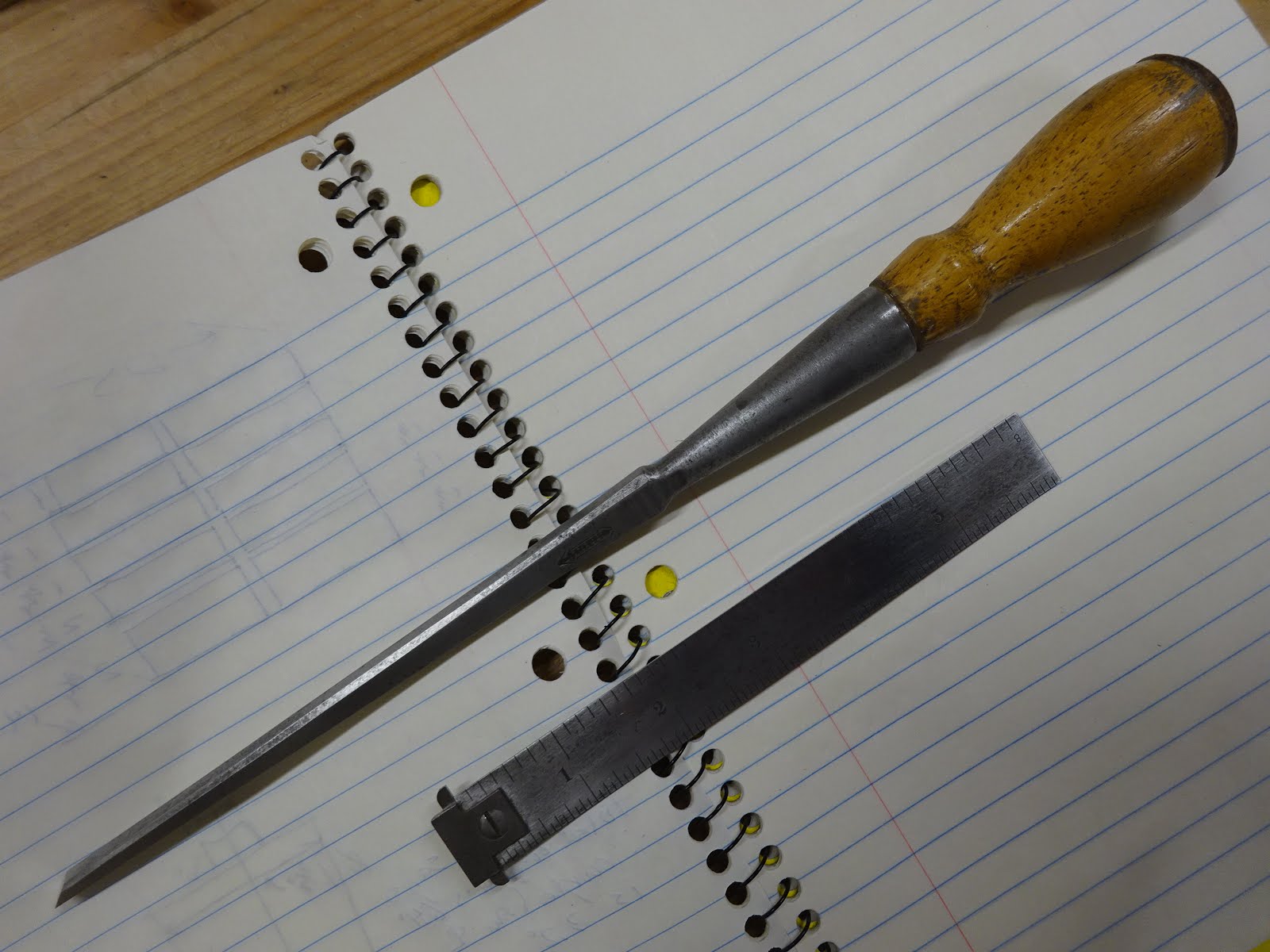
One of the chisels I got when I became the new caretaker of Orvil Heft's tools was this 1" chisel by Jaxon.  I haven't been able to find much information about Jaxon.  Perhaps they were a hardware store that had someone else make chisels for them.  I did see somewhere on the 'net a drawknife that the seller said was made by Greenlee for Jaxon in the 1950's.  Maybe this chisel is similar.
Fairly mangled handle
Maker's mark?
Handle in tough shape - you can see a hole where someone put a screw to hold it together
Some serious pounding went on in this chisel's lifetime
Now that I have lathe capability, I've been re-handling some chisels that have needed it for a while.  I thought I'd try to duplicate the original handle.
As before, first up was to fit the socket - black marks show where it's too tight
The rest was pretty easy and I'm happy how it turned out
The part of the handle that fits into the socket is fairly short on the original and I made mine the same way.  The inside of the socket showed the reason why - it was nicely conical for about an inch, but was quite uneven deeper than that.
Glamour shot
I got a comment from Bob (The Valley Woodworker) regarding the space between the handle's shoulder and the back end of the chisel's socket.  I used the original as a model for this, too.
Mind the gap!
On the new handle I left about 1/16" gap
I still have to re-handle the rest of Orvil's chisels and hopefully I'll get to them reasonably soon.
These have seen some rough use - most handles are broken or in tough shape
Orvil did a lot of fine, small carving (birds), so it's hard to imagine he was so tough on these chisels.  Maybe when he got them they were already in this shape from a prior owner who was very rough on them.

Friday, February 1, 2019

Re-Handling Two Socket Chisels

I've needed to make new handles for two chisels for a long time.  I found them both at a garage sale a couple years ago.  One of them had a detached handle and the other had no handle at all.
Stiletto at top with loose handle, unknown maker "Made in USA" at bottom
A while back, I experimented with making a handle sans lathe and had some success, but it was far from perfect.  Now with the bungee lathe it was finally time to make real handles.

First a little about the Stiletto chisel because it's interesting.
This (roughly) 1/4" chisel is quite long ...
... and very thick in cross section (this is a side view)
The part of the handle that fits in the socket was much shorter than the depth of the socket would allow
The heel of the handle has leather washers and a steel ferrule
This combination of back end hardware indicates to me that this chisel was meant to be struck with a metal hammer.  I don't believe this is a mortise chisel.  Look at this side view of the two chisels next to each other.
Stiletto at top
My best guess is that the Stiletto is a light duty mortising chisel - perhaps a sash mortise chisel.  Anyway, on to the re-handling of these chisels.
Take a known diameter rod and insert ...
... to see how far in it went (I did this with 3/8" and 7/16" dowel rods)
Got a model of the socket's interior
Then make a model of the handle and note key diameters
Mark the key locations on the blank
First thing to do is to shape and fit the socket portion.
This took multiple iterations of shaping and testing the fit.
Once the socket part fit properly, shaping the rest was reasonably easy
(and this was literally about the third piece of wood I've ever turned)
I first made a practice handle in some scrap oak.  That came out so well, I almost used it as the final handle.  But it had some plugs that filled holes, so it didn't look very elegant.  And I wanted to use some cherry for looks.
A final fitting before adding some finish
A still-wet coat of BLO - used three coats total over three days
(Excellent use of binder clips, huh?)
The old Stiletto handle was quite short.  I made the new one about an inch longer.
Old and new handles for the Stiletto
And finally, here are the two chisels with freshly made handles.  I'll have to see over time how the cherry holds up.  But I might not be bashing them with a mallet too much.
Glamour shot

Friday, January 25, 2019

Re-Handling a Tanged Gouge

One of the tools that was in the box of tools I won in an auction recently was a Buck Brothers gouge.  The business end just needed some cleaning up, but the handle was in sad shape.
Buck Brothers 5/16" radius gouge
Buck Bros logo
The handle was cracked and had black cloth tape wrapped around the "ferrule".  When I took the tape off, I found this.
Homemade "ferrule" made from wire
Apparently the original ferrule broke and the handle cracked (who knows - maybe simultaneously?) and a previous owner fixed it this way.
Took off the wire and ...
... the tang came out easily
The tang was pretty gnarly so I cleaned it up with a file
This shows the tang hole, the crack and the original lathe chuck marks
The back of this gouge was interesting.  There is a leather washer on the back end.
The leather is about 1/4" thick
It's actually two pieces of leather
They came off fairly easily - perhaps originally glued with hide glue.
The end tenon of the chisel handle was 1/2" diameter.
Well, having just built my bungee lathe, making a new handle was my first turning project.  It's a rather unremarkable handle, but so are my turning skills.  I wanted it to be shaped like my other gouge handles - just a gentle bulge in the middle of the handle's length.
Turning the new handle from mystery wood
(possibly some kind of mahogany - it was a piece of an old coat rack)
I turned a 7/8" cylinder at the left end that would receive a ferrule.  That's the same size as the original handle.  Unfortunately it looks too clunky to me.  The bolster is much smaller - about 1/2" across and the transition doesn't seem to flow just right (see pics further down this post).

When it came to fitting the tang, I used a technique that I learned from a Bob Rozaieski video.  I drilled with three sizes of drill bits, successively deeper as the drill sizes got smaller.  Then used the tang to ream the hole until the bolster was about 1/8" from the handle.
Handle perfectly level in vise
Small bubble level on the top of my drill makes it easy to judge level drilling
Using the tang to ream the hole
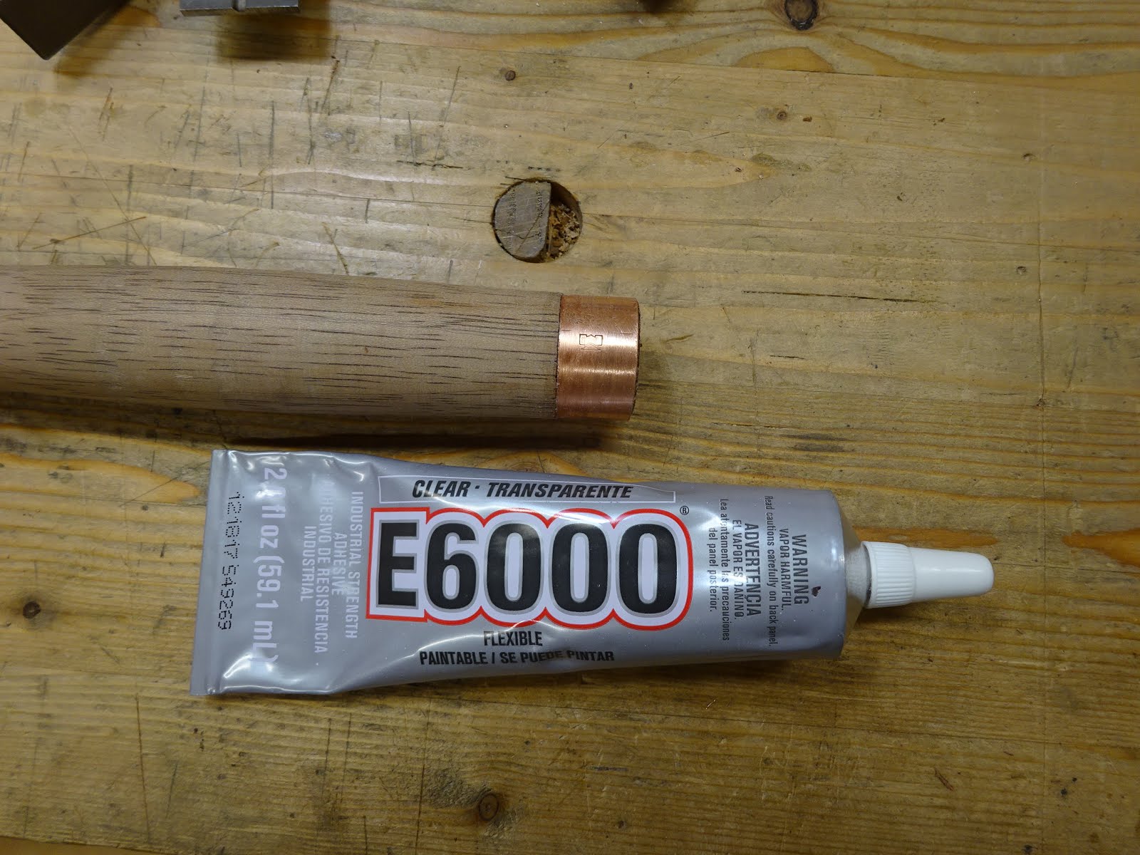
My ferrule was a piece of a copper plumbing connector cut to 5/8" long.  I made the ferrule area on the lathe just a tiny bit too small, so had to use some glue to affix the ferrule.
Ferrule attached
With the ferrule attached, I whacked the handle home and I now have a new gouge handle.
Thar' she blows!
This was literally the first or second piece of wood that I had ever turned, so it's not perfect.  And putting a few coats of BLO on it seemed to highlight some not-so-pretty area.  But I'm pretty happy about it anyway.

I love putting old, neglected tools back to work - can't wait to use it.

Friday, January 18, 2019

Bench Top Bungee Lathe Details

In my last post about the bungee lathe I promised to give some construction details, so here they are.
The bungee lathe
I started by squaring up a piece of 18" x 5 1/2" x 1 5/8" thick redwood for the headstock.  I wanted the pointed center of the headstock to be about 7 1/2" above the rails and I wanted a few inches of wood above that.  The rails take up 2 3/8" of the 18" height and what's left is held in the vise.  The 5 1/2" width is more than really needed, but I think having that width held in the vise helps keep the lathe from bending in use.
A 3/8" lag screw sharpened to a point provides the drive center
The rails are 22 1/4" x 2 3/8" x 3/4" thick red oak.  The tenons that fits into the 1/2" headstock  mortises are one-sided tenons.  That is, there is only a tenon cheek on one side, so they are basically a long rabbet at the ends of the rails.  I did it this way for ease of laying out the one inch spacing between them.
Spacing between the rails
Same spacing on back of headstock due to one-cheeked tenons
When I glued up the rails and headstock, I was very careful to keep the rails parallel.  When the lathe is held in the vise, the bottom edges of the rails sit directly on the vise chop.  The location is such that the bottom of the headstock almost (but not quite) touches the vise's stability rods.

The length of these rails allows a maximum turning length of about 15".  I didn't work this out ahead of time - it was just a couple lengths of oak that were available.  If and when I ever need to turn something longer, I'll just have to build something bigger.

At the other end of the rails is a 1" thick piece of poplar that is screwed in place and this keeps the rails spaced 1" apart along their whole length.
Spacer at the tail end of the rails
This spacer is also used for attachment of the leg that supports the tail end.  That leg is a 40 5/8" x 2 1/2" x 1 1/2" piece of redwood that I had used for something else years ago and for which I had cut out two notches.  Turns out one notch was just about in the right location for it to fit around the rails and spacer.
The leg with it's countersunk lag screw
Closer view of upper portion
Attached to the rail-spacer-rail
I cut the leg a little too short on purpose and I use shims to make the floor contact.  This was in case I move the bench around and the uneven floor causes problems.
Bottom of the leg shimmed
When the leg is shimmed and the lathe is held firmly in the vise, it's really solid.  The tail end barely moves when pushed.

The puppet, or tailstock, is a 17" x 2 13/16" x 2 1/2" thick glue-up of redwood.  Its 1" thick tenon that fits snugly between the rails is 6 1/2" long.
Tailstock, or puppet (or is that "poppet"?)
To find the location for the mortise that would hold the puppet in place with the aid of a wedge, I put the tailstock in place between the rails and marked a line at the lower edge of the rails.
The upper pencil line is the location of the bottom edge of the rails.
The lower line is angled for wedging and is 1/16" further from the upper line at front than it is at the back.
Notice that the mortise was cut about 1/8" above the upper line.  That places the upper 1/8" of the mortise within the rails.  Without an offset, the wedge would not be able to tighten the puppet properly.

This 1" wide mortise is cut into the 2 1/2" wide tenon, but it's not centered.  Rather it's placed more forward so that there is more tenon shoulder behind the mortise than there is forward of the mortise.  This will help to resist the backward force of holding the turning work between centers.

The center is another 3/8" lag screw and it's location was not measured, but determined by putting the puppet in place, sliding it up to the headstock and butting it up against the headstock's point to provide an exact location.
Finding the location to drill the tailstock (left) from the headstock's point
The wedge is a 5 3/4" long x 1" thick piece of poplar, planed to match the angle of the mortise.  It's 1" wide at the small end and 1 3/8" wide at the large end.  It was originally longer and was cut to length after final fitting to the mortise.  The final length allows about 1 1/2" to stick out at front and back when tightened.

The tool rest has a base and an upright.  The base is 7 3/4" x 2 1/2" x 3/4" red oak, slotted for the 1/4-20 bolt that would hold it to the rails.  The head of the bolt is housed in a wider slot that is sized so that the bolt head won't turn when tightening the nut.
The toolrest
The upright is cut from a 6 3/4" long x 7 1/2" wide x 13/16" thick piece of maple.  The grain is oriented vertically so that the surface that tools rest on is end grain.  I'm hoping this will be more durable.  The top end grain area is rounded and sanded smooth.  The tool rest is sized to have it's top at the same height as the drive centers.
Side view of upper portion of tool rest
The maple upper part is joined to the base in a shallow rabbet and held with screws.
Tool rest joint

The nut that tightens the toolrest to the rails is a 2 1/2" x 2 1/2" x 3/4" piece of red oak that is tapped for the 1/4-20 thread of the bolt.

The tool rest nut
The bottom surface of the tool rest base has strips of sandpaper glued to it and this keeps it from moving at all during use.
Sandpaper keeps the rest from moving in use
The treadle is a 31 1/2" x 1 3/8" x 3/4" piece of pine that is screwed to the short side of a 14 1/2" x 7" x 3/4" piece of plywood.  That piece of plywood is hinged to a larger, 23" x 19" x 3/4" piece of plywood that I stand on when turning.  My body weight keeps the treadle from inching forward as I turn.
The treadle viewed from the turner's side of the lathe
And a view from the other side showing the hinged parts 
The nice thing about this lathe is I can disassemble the leg and stow the lathe easily.
Upper part of lathe stored in a shelf
Leg and treadle assembly stored beside parts cabinet

With the exception of the hinges, this lathe was built from materials I had on hand.  So total cost was about $5.  Well, that's all I can think of.  If anyone has questions, please ask.  Next time I'll show some of my first turnings.