In the first part of this series I wrote about fixing the broken screw arm post, removing a section of damaged or missing threads on each screw arm, and patching and re-drilling the hole for the depth adjustment locking thumb screw. Those things allowed me to test the plane out, as I successfully plowed a 1/2" groove.
 |
| First and only test groove made two years ago |
I knew then that there were other things that needed attention and I'm finally getting to them, as I'd love to get this plane into regular use with the new smaller-width irons I recently purchased.
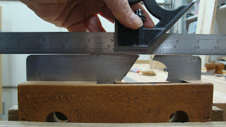
There is nothing square about this plane. Maybe things were square when it was built, but now - not so much. I though a lot about what surfaces should be square and flat and decided on a few. First was the fence. The face of the fence that rides on the workpiece should be flat. And it should be square to the top surface of the fence where the screw arm posts are attached.
 |
| These two surfaces should be flat and square to each other |
Here's a closer view of the end grain of the fence. Check out the boxwood section dovetailed into the bearing face of the fence.
 |
| Boxwood wear surface was let into the fence |
Boxwood is used because it's a lot tougher than most woods. But this plane was apparently used extensively. If you look closely, you can see the boxwood surface is concave. It was worn down so much, the whole of the boxwood surface was far lower than the beech area, which would never touch the workpiece except when plowing very deep grooves.
 |
| That's a lot of daylight under the square |
After planing down a couple of high spots, I checked for twist.
 |
| Holy crap, Batman! |
I worked the two surfaces until they were twist-free, flat and square to each other. I was pleasantly surprised at how easy the boxwood was to plane. I thought it might be like planing purple heart or lignum vitae (neither of which I've planed, but have heard they're very hard). But it planed beautifully.
 |
| That's better |
The next area I worked on was the bottom surface of the plane body and the side wall to which the skates are attached. I first glued a small crack that I saw on a fragile area that could have popped off while planing. There was evidence that this area may have been patched before.
 |
| Arrow is at most fragile point |
I got the bottom flat and twist free, as well as square to the adjacent wall. This made the skates perpendicular to the bottom surface. Prior to working on that sidewall, the skates were not in perfect alignment with each other. But they are better now that the wall to which they are attached is flat.
 |
| Checking alignment by looking from end |
 |
| And checking with a straight edge |
The bottoms of the skates that ride on the workpiece have a convex curve. I need to file them flat and parallel to the plane body's bottom surface. I'll get to that later.
One more area where flatness and squareness are important is the bottom of the screw arm post. This surface mates with the upper (and now flat) surface of the fence. Not only should this surface be flat, but it should also be parallel to the screw.
 |
| Testing for flatness with a straight edge |
Neither post had a flat bottom surface, so I marked high spots and started removing material. At first I used a block plane, but the surface is so small that I couldn't control the plane well enough. Then I tried using a scraper to remove high spots, but that also wasn't good enough. I finally went with sandpaper, pulling the arm assembly over the sandpaper to flatten it.
 |
| Flattening the bottom of the arm post |
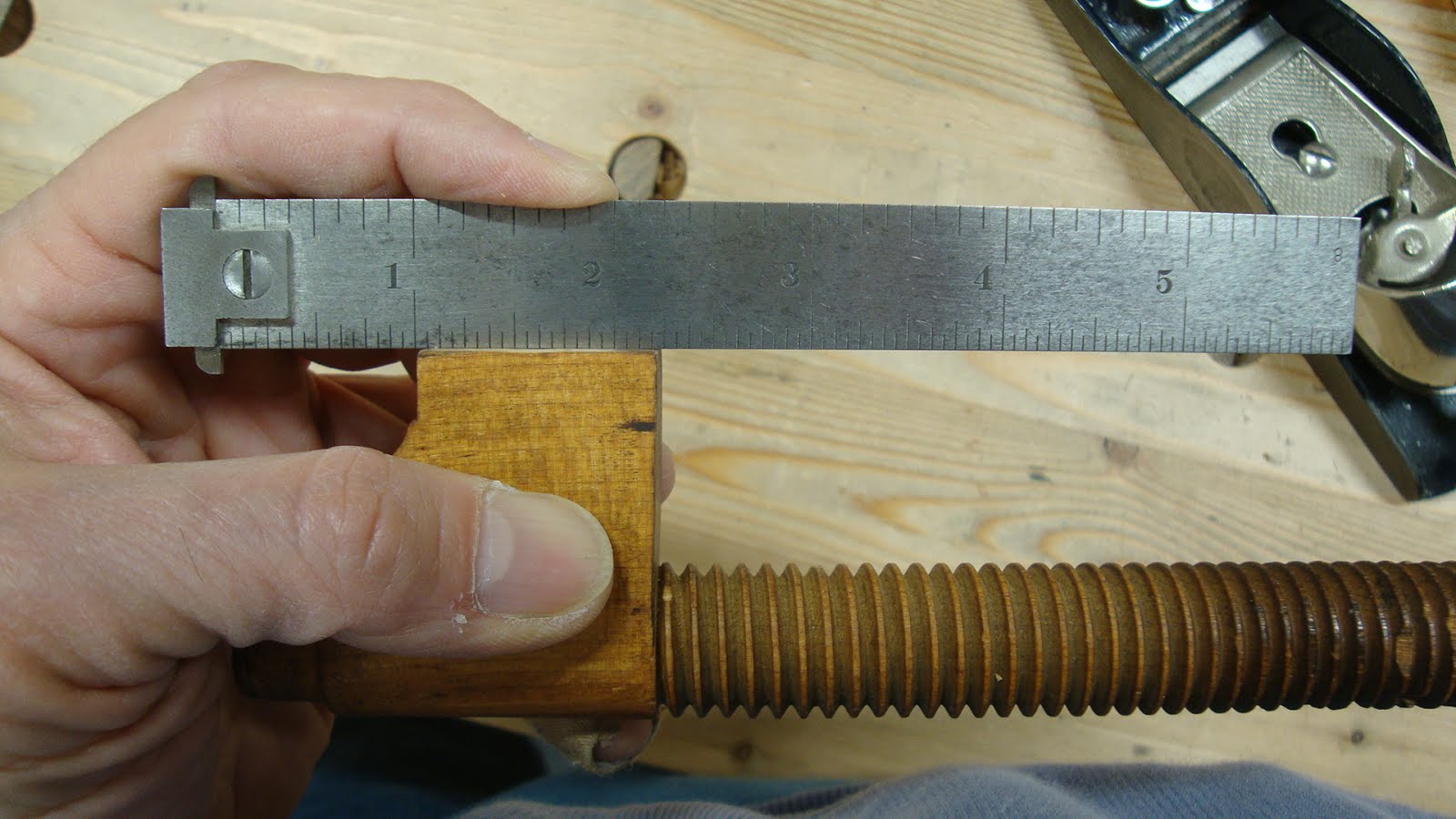
I checked that the bottom was parallel with the screw by holding the post flat on the work bench and gauging with a ruler at both ends of the threads.
 |
| About 1 1/8" here ... |
 |
| ... and 1 1/8" here |
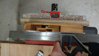
I assembled them with the fence and used winding sticks to see if the two screws were parallel with each other.
 |
| Shocking!! As good as I could have hoped for! |
I was very satisfied with this, but I'll still need to see if the fence's bearing face is parallel to the skate when the plane is reassembled. If not, I'll tweak the bottoms of the posts to get it right.
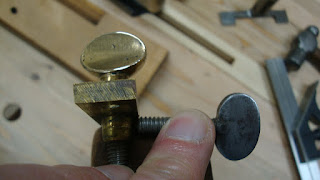
Aside from all these out-of-square issues, there was a small problem (that could be a large problem later) with the depth adjustment. The mechanism works fine, but the mortise that houses the brass plate that is screwed to the plane body is damaged.
 |
| Plate not seated properly in mortise |
 |
| Rear aspect of the area - note the crack at bottom right |
 |
| Front aspect - smaller crack bottom left |
I believe the locking screw has been clamped so hard on the depth adjuster that it has blown out the thin wall on the left side of the mortise (at the bottom in the above pictures). You can see the crack that has formed, especially at the rear. The locking screw works as in the following picture.
 |
| Locking thumb screw pinches the brass portion below the plate so the adjuster can't be turned |
 |
| It pushes the whole mechanism against the thin wall at left side |
In the following picture, I've removed the screws and pushed the adjuster into its proper position.
 |
| Adjuster in proper position |
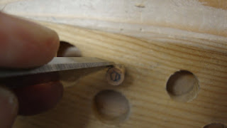
If you look closely into the screw hole, you can see the hole has been worn to an off-center position.
 |
| Can see the hole in the plane body is off-center from the brass hole |
So I decided to drill out the screw holes, plug them, and re-drill them, hopefully with better centers.
 |
| Cutting some plugs in beech - needed two for each hole to get enough length |
 |
| Shaved them a bit since they are tapered from the plug cutter and I don't want to wedge the plane body apart |
 |
| Two plugs glued into each hole |
I used a router plane to flush them up after the glue had set. Notice on the sidewall down inside the mortise hole there are drops of glue squeeze-out. Apparently the stresses applied by the locking screw were enough to crack apart the body in this area. So I clamped the whole plane body in a bench vise until the glue set up. Maybe the glue that squeezed into the crack will seal it.
When the glue had set, I drilled new holes for the screws, trying to be as accurate as possible. I also tried to get some superglue into the cracks along the thin wall and clamped it in the vise to pull that wall back in.
 |
| Holes drilled and superglue applied in cracks |
Finally, I glued a couple of thick shavings into the void on the left side where the plate had shifted to. The depth adjuster is being used as a clamp to hold these shavings in position.
 |
| Shavings glued into to open area on left. |
And here's how it came out. The cracks near the thin side closed up a bit and the whole mechanism is in a better position.
 |
| Looking much better |
 |
| Blurry pic from the other angle |
After the plane was reassembled, I checked the fence for parallel with the skates. Couldn't be happier with that.
 |
| Looks pretty good, but lets measure |
 |
| Just shy of 12/32" at top |
 |
| Just shy of 12/32" at bottom - BANG ON!! |
The the skates had to be filed flat and parallel to the bottom of the plane.
 |
| Before filing - lots of light coming through at front and back |
This took only a few minutes with a flat file, followed by light sanding. Then it was time to try making a groove. Still using the original (to me) 1/2" iron, which was perfectly sharp from a couple years ago.
 |
| Not bad |
I started at the far end and gradually moved backward, taking longer shavings. It was little difficult and the iron dug in and removed too much material at the far end. But I can tell this plane will require practice. And I can't wait to see how it works with the narrower irons.
The next post will be about the irons and wedge.