Warning: long post (at least there's lots of pics).
OK, so square patterns were challenging, but not too bad. Moving on to patterns based on 60° joints is a whole other ball game. At times it reminded me of how tough it was when learning how to make wooden screws. But just like that time, things come with patience and work.
In this post, I'll share how I went about making the frame. Fitting in the "loose" pieces (those fill-in pieces that aren't joined using 60° lap joints) is basically the same as for square-based kumiko, only we use a jig for trimming 30° and 60° angles.
My first woefully inadequate attempt started with a jig similar to that for making the square frames, but with a 60° angle. That jig has since been destroyed, but it was like this sketchup drawing.
 |
| First 60° jig |
It's a piece of wood as a base, a 1/2" x 3/4" stick glued to it with a couple of kerfs cut at 60°, and a stop block. This was sufficient to get started. With the help of a spacer block, I could cut two kerfs in a workpiece to create a half-lap cut-out, into which another workpiece would fit.
 |
This picture was from the square-based kumiko, but same concept for 60° cuts:
with spacer block in place, make a kerf in the workpiece, remove spacer block,
butt workpiece against stop block and make another kerf.
(spacer block was thinner for the 60° kumiko, approx. 0.112") |
With this jig I was able to get a few sticks lap-joined. But there was a problem ...
 |
Four lap joints assembled, but see the clear 30-60-90 triangle?
The structure was a little off of 60° ... |
 |
| ... and that made it more problematic to fit the insert pieces |
I was hoping that I could use this slanted grid with some fill-in pieces to get a hexagonal structure. But doing it this way, the grid was flimsy and would not hold the proper shape. I realized that this was not the way to go, so I did some more research. People make hex kumiko with 3-way joints. And there is more than one way to get that joint. I settled on one that I saw in this kumiko video. This is an excellent tutorial for doing hex kumiko with hand tools.
I ended up doing things a bit differently from the author of that video, but it worked - after several failed attempts. First I did a larger mock-up. Working on 1/2" x 1/8" kumiko sticks is challenging, so I started with some 3/4" x 1/4" sticks - MUCH LARGER in comparison. Here's what the three sticks need to look like:
 |
| Piece A gets a 60° lap joint on top and bottom - each about 1/3 the depth of the piece |
 |
The other two pieces (B) are identical:
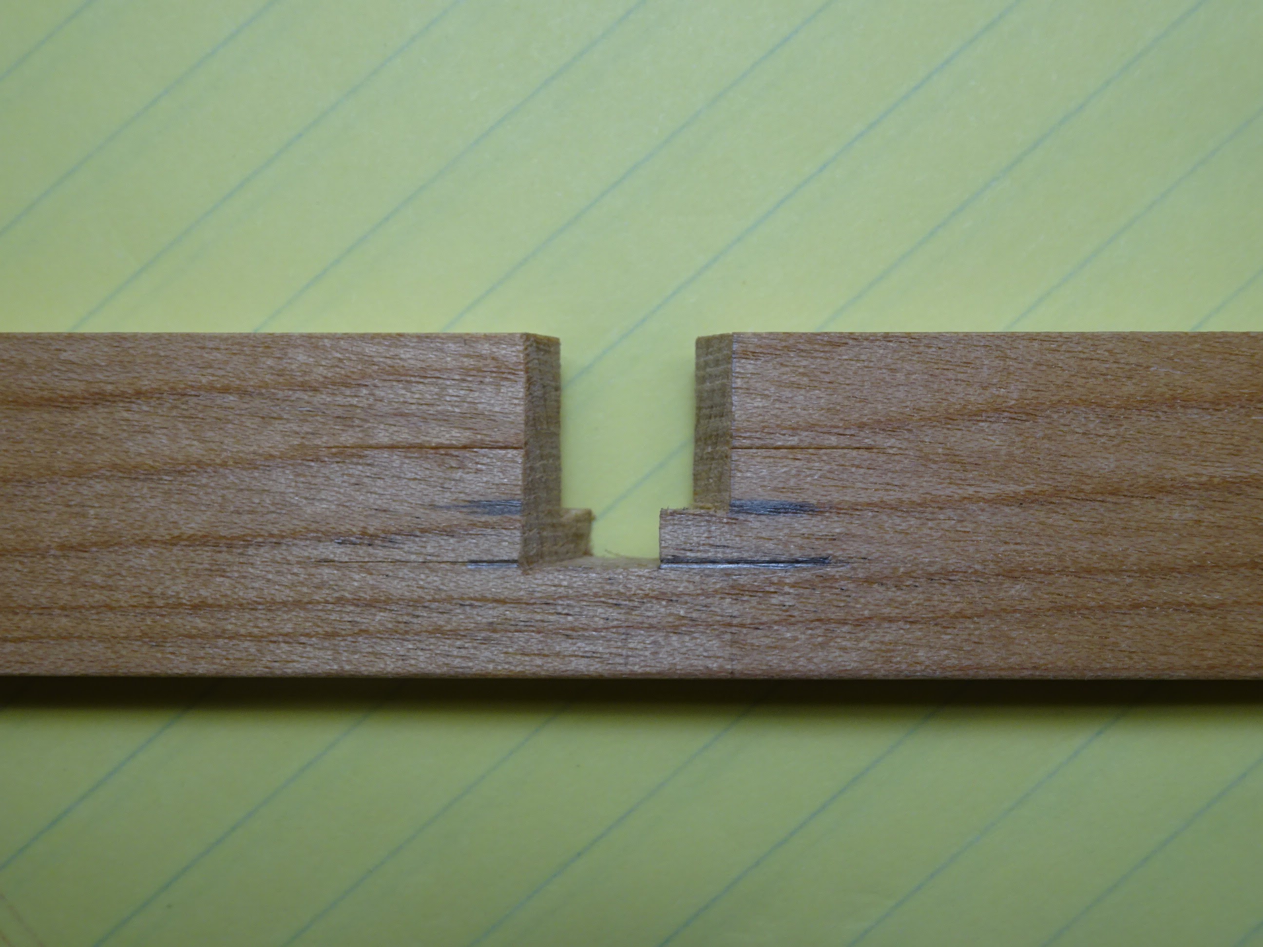
There are 60° cuts from both directions, one cut only 1/2 depth of the piece,
the second cut 2/3 depth of the piece. If this is cut properly, the little points
formed where the two cuts intersect are exactly in the center of the workpiece's thickness. |
 |
| Photo of piece B from the side |
 |
| Placing piece A on one of the B pieces |
 |
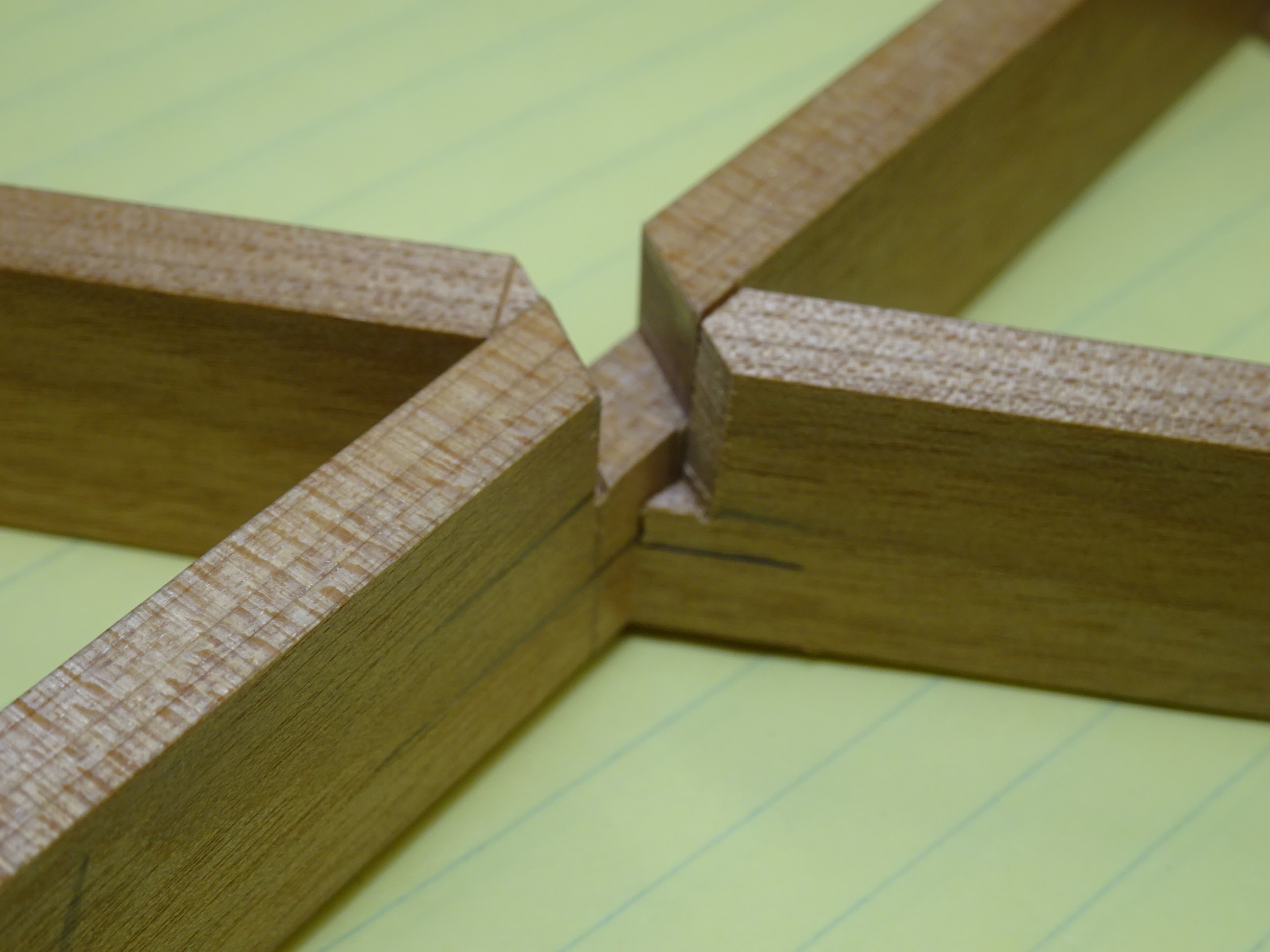
Leaves a slot for another B piece to fit from above.
Note how the two surfaces that make up one side of the slot are nicely in line. |
 |
| And there's your three-way joint |
Like I mentioned, it's tougher to make these joints in smaller stock. The video's author used a cutting jig similar to what I showed above, but he also measured distances and used a marking knife to mark where the cuts would start. I wanted a cutting jig that would eliminate the need for measuring and using a knife. Eventually it was successful, but not without a few failures ...
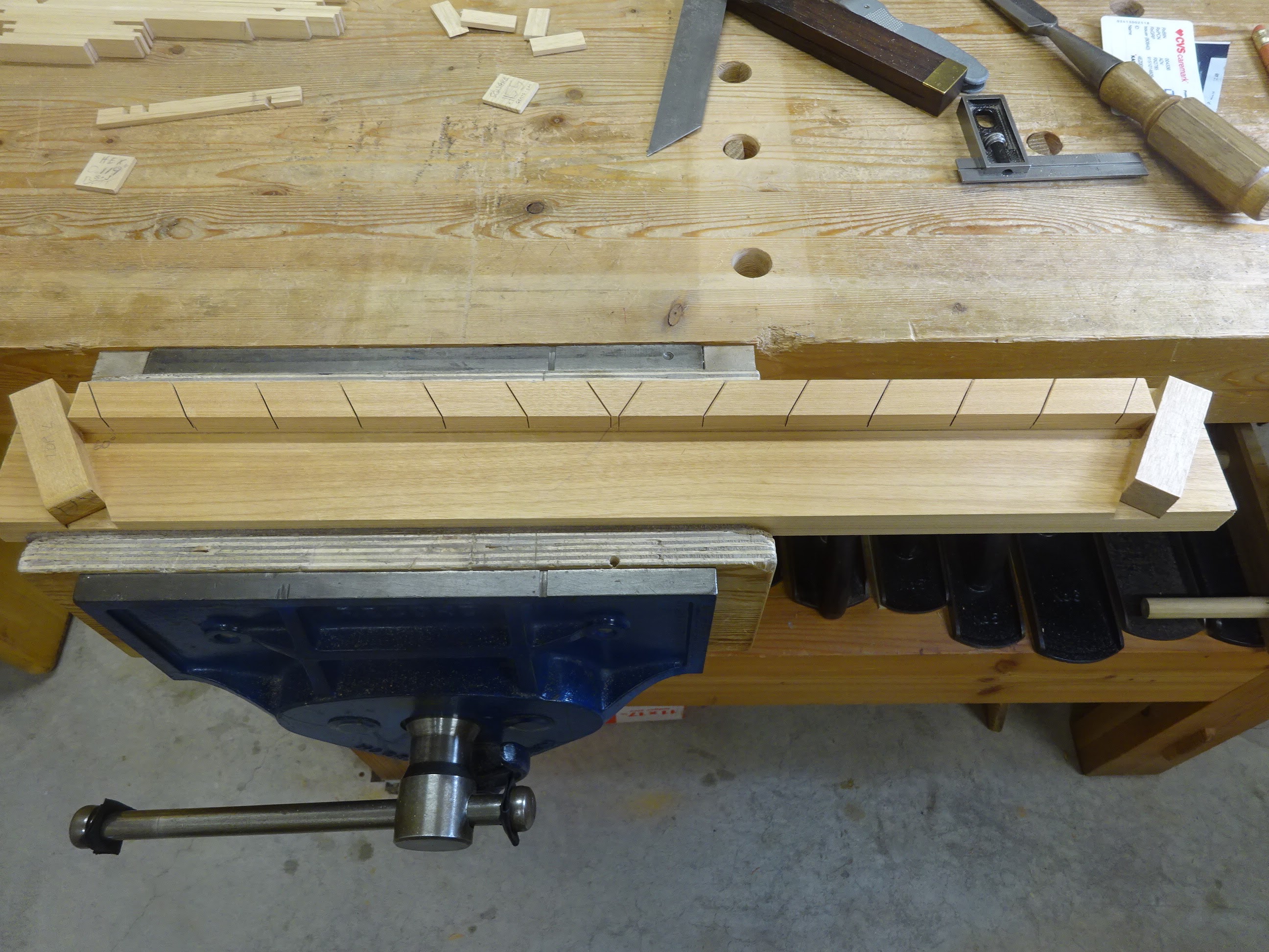
Here's the first version of the jig. It's a base, a 1/2" x 3/4" stick glued to it and stops that are housed in 60° dadoes at each end. The stick has 60° kerfs cut into it at exact intervals. Here's a key point: the far right and far left kerfs have to be EXACTLY the same distance from their associated stop blocks. And then the succeeding kerfs have to be EXACTLY the same distance from each other.
In the first attempt, I spaced the kerfs by cutting the outer-most ones a measured distance from the stop blocks, then each successive kerf was marked using a block marked with a knife line as shown below.
 |
| With a card stuffed into the kerf, block pushed up against the card, marking next kerf |
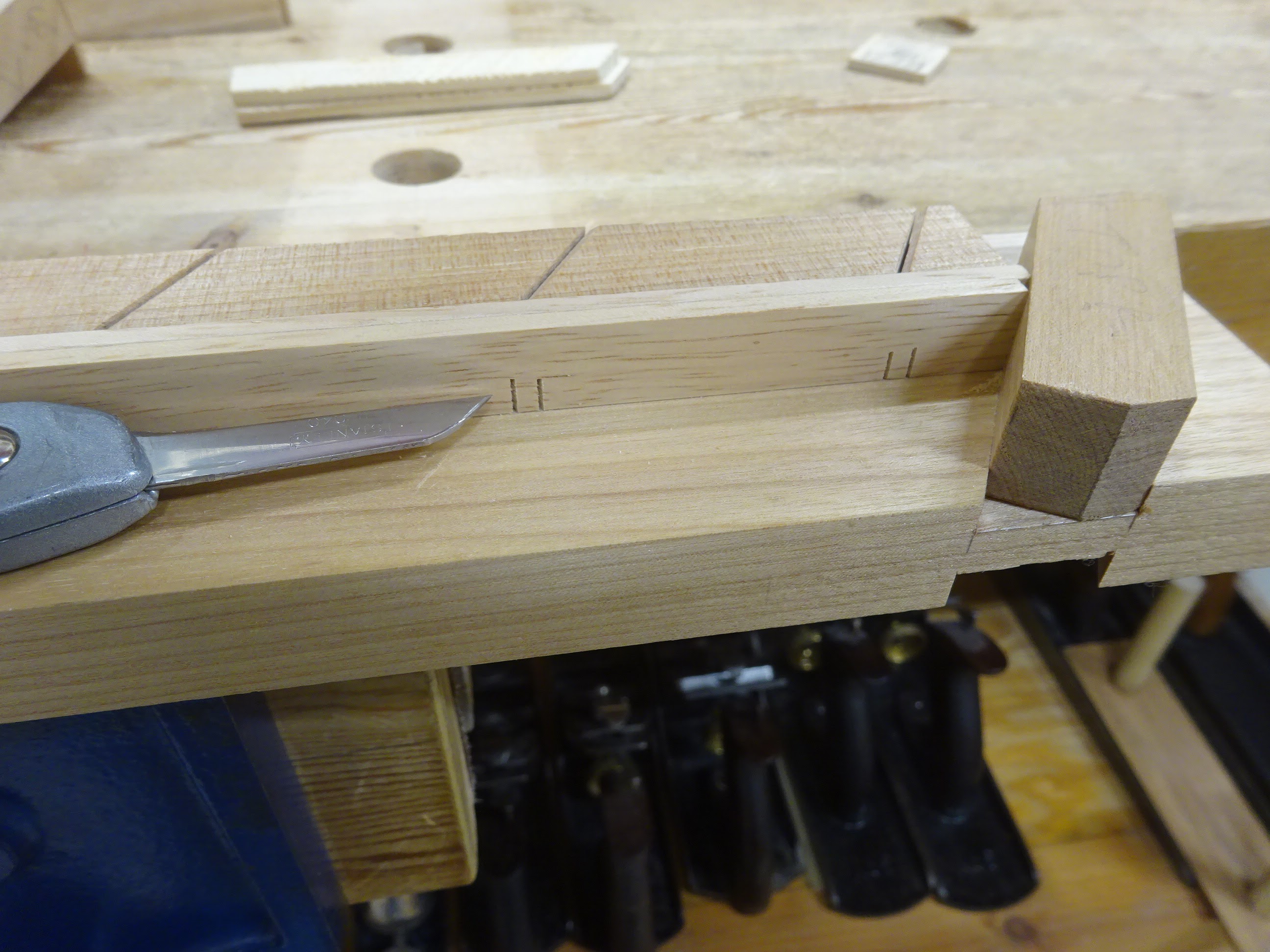
When using the jig to cut kumiko workpieces, I needed something to limit the depth of the cuts. I used two pieces of wood, each planed to about 1/3 the width of a kumiko piece, and used them to limit the saw cut into my kumiko pieces. For the "A" pieces, the cuts needed to be 1/3 down, so I used two of these "depth gauges". After the first cuts are made, the A pieces are turned upside down, butted up against the right stop block again and laps made on the other edge.
 |
| Cutting kumiko pieces to a depth: I stop when the saw starts cutting into the depth indicator strips |
 |
| A few of the "A" pieces cut |
The "B" pieces have 60° cuts made 2/3rds down, then they are flipped end-for end and butted up against the left stop block. The kerfs that had just been cut remain facing up.
 |
Ready to make the second cuts in the B pieces.
These cuts will only be half way down.
|
After cutting those, removing the waste and test fitting, I found that my jig was not nearly as accurate as I had hoped. Some of the joints fit OK, but at some point I messed up with one of the kerfs in the jig and some joints didn't have a chance.
 |
Pencil shows an A and a B fit together, but the kerf surfaces don't meet up
and a third piece will not fit together with them. |
 |
| You can see here that the point of this B piece is not well centered |
I remade the jig and tried to space the kerfs more accurately, as well as trying a different method to get the first kerf at each end the exact same distance from their respective stop blocks. First I tried using gauge blocks, but this didn't help and I ran into similar problems.
 |
| Using gauge blocks to determine where to make the first kerf in the jig |
After scrapping another jig, here is what worked. I butted a ruler up against the stop block and used a knife to nick the jig's first kerf location.
 |
| Using the width of a ruler to set location of first kerf |
 |
| Bevel gauge set at 60° to mark the first kerf at the knife nick |
 |
| To mark succeeding kerfs, I used a carefully planed stick to get kerfs exactly 2" apart |
 |
With knife in the first marked line, slide the bevel gauge and stick over to the knife,
then remove the stick and mark the next kerf using the bevel gauge |
After marking lines as far as the lateral center of the jig, I chiseled a trench on the stop-block-side of the knife lines.
 |
| Trench chiseled to right of these lines |
 |
| Then slid a vertical cutting "helper" to the knife line ... |
 |
| ... and made the kerf |
This little cutting "helper" was KEY. I planed its sides exactly 60 degrees to its back edge and it's sides were precisely square to the bottom. A small piece of wood is glued to its back edge to act as a fence. You can see in the above pics how the helper is used to saw perfectly vertical kerfs that are exactly to the right of the knife lines.
I then repeated the same procedure for the left side of the jig, with the 60° cuts going the other direction. Here's the jig in action.
 |
Butt a couple of workpieces against the stop
(OK I forgot to show this with the lap-joint spacer in place) |
 |
| Use the knife to locate the cutting helper at left side of the kerf |
 |
| Make the cut (here, I don't have the cutting depth indicators in place) |
 |
OK, now with spacer and depth indicators in place, make the second kerf
(knife pointing at spacer) |
 |
| And now here are some evenly spaced kerfs cut on one side of "A" pieces |
 |
Next flip the parts upside down and butt them against the stop block
(guess what, forgot to show the spacer in place again) |
 |
After making the cuts, now have upper and lower 60° lap joints.
The lower cuts are in the direction the knife is pointing. |
 |
| Using the depth indicators as a platform, chisel out the waste |
 |
| And you get some nice evenly spaced "A" pieces |
Now, for the "B" pieces.
 |
| Use just one thickness of depth indicator to cut 2/3 down the workpiece |
 |
View from above: make the pairs of kerfs as for the A pieces, just a bit deeper
(note: the workpieces in this photo are marked A and B to show their orientation in the next
photo. These letters have nothing to do with being piece type A or type B) |
 |
| Flip them end for end and butt them against the left stop (kerfs still up) |
 |
This time use a depth indicator to cut 1/2 the width of the workpieces.
Make the pairs of kerfs. |
 |
Remove the waste using the half depth indicator as a surface for the chisel to
reference on |
 |
| Then switch to a 1/3 depth indicator and remove the deeper waste from the first cuts |
 |
| This is what the B piece will look like |
The last picture above shows nicely centered points on these B pieces. Assembling the pieces was exhilarating. They fit together a bit tight. Individual pieces fit together perfectly, but when multiple pieces were assembled it was a little tough going.
 |
Tight enough that one piece broke - shows that strips used for kumiko
would best be made from straight-grained stock |
 |
| Can you see a hexagon in there |
To make the fit a bit easier, I changed the spacer block used to create the lap joints from 0.112" thick to 0.117" thick. Fortunately the whole jig didn't need to be remade to do this - just changing the spacer block was enough. And it worked great. Just a few thousandths of an inch allowed the joints to fit together more easily.
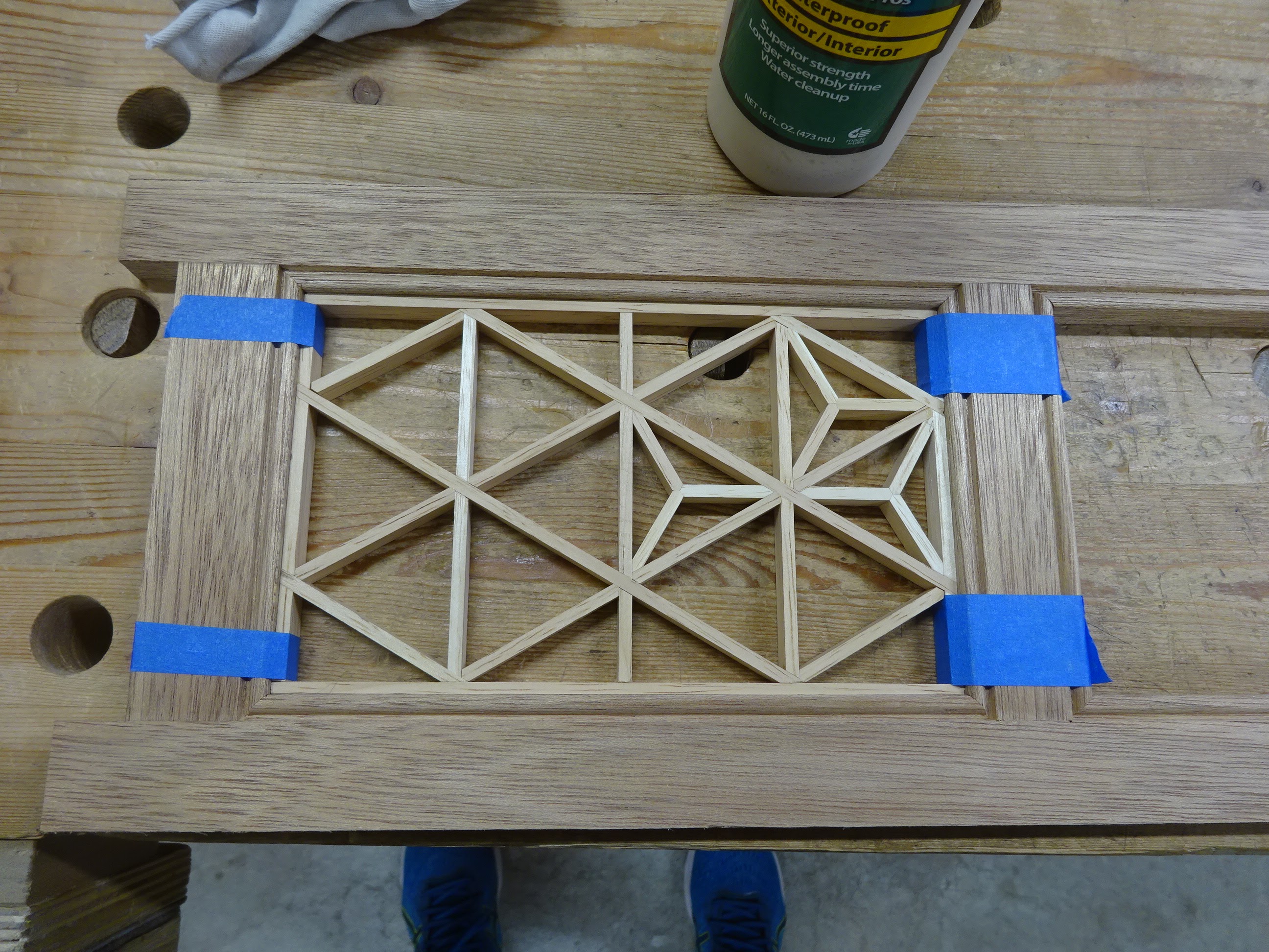
So, what will I do with these square-based and hexagon-based kumiko pieces? No plans just yet. Some can be used as wall art or as trivets for hot pans or dishes on the dinner table. Small patterns could be use as coasters or even ornaments. I am planning to make a new small cabinet for the bathroom that could have kumiko in the door panel. Lots of possibilities.
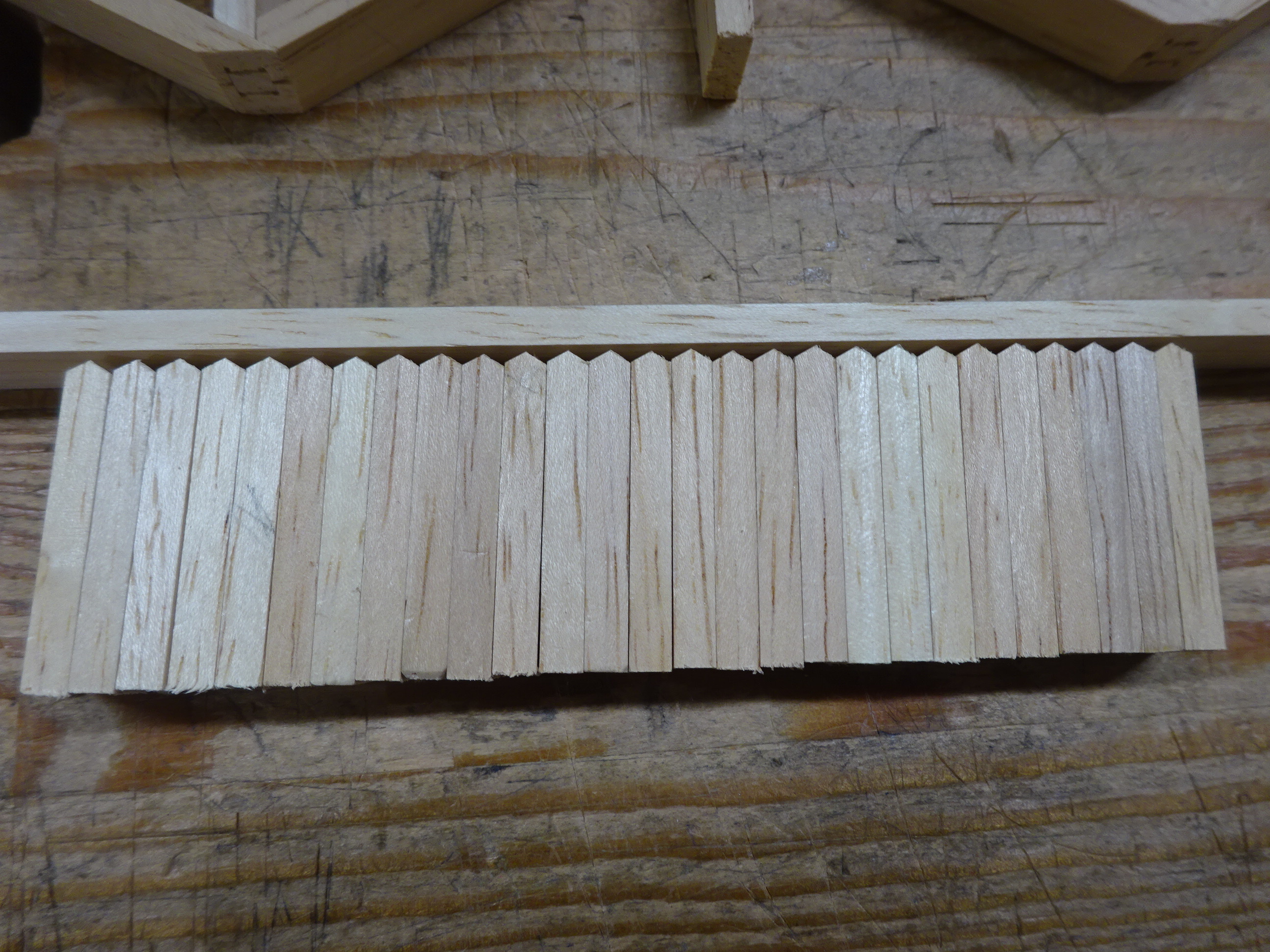
One thing is a bit more certain though. I might not do more kumiko until I have room for (and purchase) a bandsaw. Making the strips is a chore.