Thursday, February 28, 2019

Wooden Jack Plane Build - Prototype #2

Well, the first prototype in pine worked, but the mouth was huge.  And while a jack plane doesn't need a tight mouth, I wanted to do better.  Also, I wanted to do some work with a tote and practice the shaping details on the body.

To tighten up the mouth, I searched the internet and once again Bob Rozaieski came through for me.  Bob often seems to have the information I need and that's why I support him on Patreon.  His post from May of 2017 on Wooden Plane Throat Geometry showed exactly what I was looking for.  And though his post was about smoothing planes, he told me the same ideas hold for larger wooden planes.

This time I made my plane blank from poplar.  After sawing off and planing the sides, I cut the main body apart.  I used a 45° bed angle, a 60° breast angle and a wear angle of 100°.  But this time, the wear is taller.
Left side of plane is removed, bed is to right and breast and wear are to the left
Notice how short the wear was on the first prototype
In the first picture above, you can see the abutment recess drawn in.  Note how the fore part of the abutment does not go all the way through to the mouth, but rather it ends in the middle of the wear.  And you can see how small the mouth will be.
Here I've moved the breast/wear section of the main body to the left, revealing
the overall shape of the abutment recess
This complicates the making of the plane slightly, as one cannot saw the front abutment shoulder like you can with the rear shoulder.  But chopping, paring and leveling with a router plane is fairly quick.

After that I made a wedge and planed it to fit.  I shortened it a little bit at the small end so that it would not run into the "wear" portion of the abutment recess.
Fore section of main body removed to show fitted wedge
Here's a close-up shot of the wedge (right) extending just to the wear section of the abutment recess
I cut the wedge a little shorter and then did the rest of the shaping on the wedge.  Then I prepared the blank for glue-up.
The body and sides are taped together from below to prevent moving while gluing together
Once the glue dried, I cleaned up the outside surfaces and cleaned up any glue that squeezed into the throat.  Then put in the iron/cap iron and wedge to see what the mouth looked like.
You can see the mouth opening at bottom of the throat.
It came out just about how I wanted it.
Here's the mouth from the sole - fairly tight, but allows thick shavings to pass through
When I gave it a try, I got nice thick shavings with no clogging.
First shavings
The next thing was the handle/tote.  I love the comfort and shape of the tote on my early 1900's type 5 Stanley #4 1/2 and I used that as a model.
Copying the tote shape from the #4 1/2
The paper template
Used the template to transfer the shape to a 1" thick piece of poplar
Then cut and shaped as best as I could.  This was time-consuming, but was a lot of fun.
Note the cutout at the bottom rear of the tote.  That's a tip I got from Richard McGuire's plane build - it allows you to fit the tote into a rectangular mortise, rather than try to shape the rear of the mortise like the rounded back of the tote.

I chopped the mortise and pared the walls very carefully and got a great fit.  Then glued the tote in with hide glue and let it dry.
Gluing in the tote
I'll close with some details on the shaping of the body for comfort.
Added the "eyes" at top of throat, which make it a lot more comfortable when retrieving shavings
The top, rear edge was rounded over, approx 3/8" radius
All other top edges were chamfered, 3/8" on sides and 5/32" on top.
And a stopped chamfer was extended down all four vertical edges about 1 1/4"
Prototype #2 all done
Next time I'm going to write a bit about the positioning of the tote and how I changed that for the real (non-prototype) plane.

Friday, February 22, 2019

Wooden Jack Plane Build - Prototype #1

I've been wanting to make wooden jack and try planes for quite a while.  A few months ago I bought the irons for them and finally I'm getting around to the build.  But because I don't want to mess it up, prototypes were in order.

Before I begin, I'd like to credit Richard McGuire, whose jack plane build videos really helped me, and Caleb James, whose published free plans for a wooden jack also helped a great deal.  I don't have plane floats, so like Richard's plane build (and unlike Caleb's), I'm using a three-piece glue-up for my design.  And like Caleb's plane (and unlike Richard's) I'm using abutments to wedge the iron rather than using a cross-bar - I much prefer abutments.  I built a wooden smoother this way last year and it turned out pretty good.  Those blog entries are here and here.
The coffin smoother in red and white oak
The first prototype jack plane is in pine.  I started with two 15 1/4" pieces of 2x lumber glued together.  After squaring it up to about 2 5/8" tall (thick) and about 3 1/4" wide, I sawed off 1/2" thick pieces from each side, then planed the sawn surfaces to get me sides that were 1/2" thick and the main body that was 1 15/16" thick.
Two sides and main body
The iron for this plane is just shy of 2 1/4" wide.  When I add 3/16" recesses to the sides (they form the abutments) to the 1 15/16" main body, I get an area that is a little more than 1/16" wider than the iron.

On the sole of the main body blank, I measured 5 1/2" from the toe to mark the back of the mouth.  Then on the sides of the blank I drew a 45° bed angle and a 60° breast angle from that spot.
Main body lines laid out
Then cut out the triangle and planed perfectly square the bed and breast
It made sense here to create a recess for the cap-iron screw.
I used chisels and a router plane
As it turns out, the slot in the iron (and hence the cap-iron screw) was not perfectly centered, but was slightly off and I failed to take this into account.  I later had to widen the recess to accommodate this.
On the fore part of the main body I added a small wear angle (bottom left)
To start creating the abutment recess on the sides, I marked a line directly from the main body bed.  I did this rather than simply marking a 45° line on the side with a combination square in case there was any deviation from the 45° bed angle after having planed it.
Marking the rear abutment recess line
Next was to figure out where to put the front abutment recess lines.  I started on paper and found that this double iron forms an angle of about 1-2° (in the opposite direction as the wedge angle).
Worked out some angles on paper with the actual iron and cap-iron
I wanted a wedge with about a 10° angle, so the iron/cap-iron and wedge combined would be about 8-9°.  I created a temporary 1 15/16" wide, 10° wedge, placed the iron/cap-iron and wedge in the plane and marked a line on the side.
Marking the forward aspect of the wedge abutment recess
Then I used a bevel gauge to make a knife line at the penciled line, sawed the shoulders of the recesses to a depth of 3/16" and removed the waste with chisels and router plane.
Far side is being held away from main body, near side is in proper placement
And here are the three parts placed together
 Then while holding the plane together, I inserted the iron and looked at the sole.
When I moved the fore part of the plane to a location that would give a reasonably sized mouth
I got the funny offsets that you see here.  I dealt with that later.
Then it was time to glue up.  I lined up the parts as accurately as I could, turned the plane upside down and placed packing tape across the bottom to hold things in the right position while gluing up.
Then turned right-side up and added glue to the sides
After clamping and allowing to dry, I cleaned up the surfaces
As for that discrepancy on the sole, ...
... I chiseled the wear back to line up with the sides
But this created a mouth quite a bit larger than I wanted
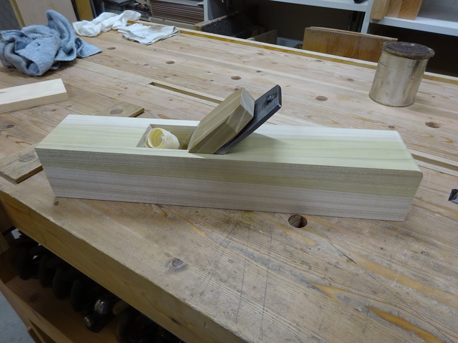
I didn't get any good pics of this, but I made a wedge out of poplar.  After sharpening the iron I took some shavings and the prototype worked nicely.
First shavings from a scrap of pine
This prototype works, but is not optimal.  Next time I'll write about what I changed to tighten the mouth.

Friday, February 15, 2019

Giving Away a 10" Brace

Of the three braces that I bought at a November auction, I'm keeping one, another I gave to a neighbor who's just getting into hand tool woodworking and the third I'd like to give away.  It's nothing special, but it works perfectly.
Dunlap 10" sweep brace
Not sure what the "F" designation means
I've cleaned this brace and oiled it, so it's working smoothly.  Both handles turn nicely.  The chuck is pretty standard and works great.  Same with the ratcheting mechanism.
I've cleaned this up since this pic was taken
If there is any problem at all, it's that the three screws that help hold the wooden top handle to its metal base are missing.  This could be fixed easily enough with three 5/8" screws of the right gauge, but it's not necessary for the tool to work.
The center hole in the wooden handle is threaded and it screws on to the metal post
Here's the deal.  I'd like this to go to a relatively beginning woodworker - someone who needs it and will use it, rather than it going to a collector (not that this Dunlap is a collector's item) who might profit from it.  The honor system is in effect.  It's a bonus if you live not too far from Mountain View, CA, but I'll ship to anywhere in the 48 contiguous states, at my cost.  So if you are interested, please send me a message using the "contact me" gadget on this blog page.

I see several similar braces on eBay for $20, so that's probably what it's worth.  But it's yours for free.  If you feel like kicking back the cost of shipping, that's fine, but not required.


UPDATE: looks like I've found a home for the brace.  Thanks to all those who showed an interest.

BTW, I also have a spare top handle and chuck with jaws and spring.  If there are any collectors out there who think these could be useful, I'd be happy to send them to you.
The spare handle is hard plastic
The spare chuck with jaws and spring - has slightly damaged threads fixable with dremel

Friday, February 8, 2019

Another Chisel Re-handling

One of the chisels I got when I became the new caretaker of Orvil Heft's tools was this 1" chisel by Jaxon.  I haven't been able to find much information about Jaxon.  Perhaps they were a hardware store that had someone else make chisels for them.  I did see somewhere on the 'net a drawknife that the seller said was made by Greenlee for Jaxon in the 1950's.  Maybe this chisel is similar.
Fairly mangled handle
Maker's mark?
Handle in tough shape - you can see a hole where someone put a screw to hold it together
Some serious pounding went on in this chisel's lifetime
Now that I have lathe capability, I've been re-handling some chisels that have needed it for a while.  I thought I'd try to duplicate the original handle.
As before, first up was to fit the socket - black marks show where it's too tight
The rest was pretty easy and I'm happy how it turned out
The part of the handle that fits into the socket is fairly short on the original and I made mine the same way.  The inside of the socket showed the reason why - it was nicely conical for about an inch, but was quite uneven deeper than that.
Glamour shot
I got a comment from Bob (The Valley Woodworker) regarding the space between the handle's shoulder and the back end of the chisel's socket.  I used the original as a model for this, too.
Mind the gap!
On the new handle I left about 1/16" gap
I still have to re-handle the rest of Orvil's chisels and hopefully I'll get to them reasonably soon.
These have seen some rough use - most handles are broken or in tough shape
Orvil did a lot of fine, small carving (birds), so it's hard to imagine he was so tough on these chisels.  Maybe when he got them they were already in this shape from a prior owner who was very rough on them.