Thursday, August 25, 2022

New TP Cabinet w/ Kumiko Door, Part 2

Last time I was figuring out how to join stiles and rails that have a bead on the inside edges.  I used a lap joint with the beaded area mitered.

Like this prototype

Making a few prototype joints was really helpful in the layout of the joints.  But I also had to figure out how to fit kumiko panels in the openings with no slop.  I agonized over this for quite a long time, but after it's done it seems so simple.  I made the kumiko panels first.  These were basically two hexagons stacked one on top of the other.

A prototype kumiko on a prototype door frame to help get dimensions

For the kumiko above, after trimming the uppermost and lowermost excess pieces, I used a combo square to mark the kumiko left and right sides for trimming, referencing off a straight bottom piece.  I marked and cut through the center of the three-way joints.  I didn't realize this at the time, but the kumiko would look much better with a vertical border strip on left and right

Here, centering the kumiko (and extra vertical border strips) on the edge of a rail

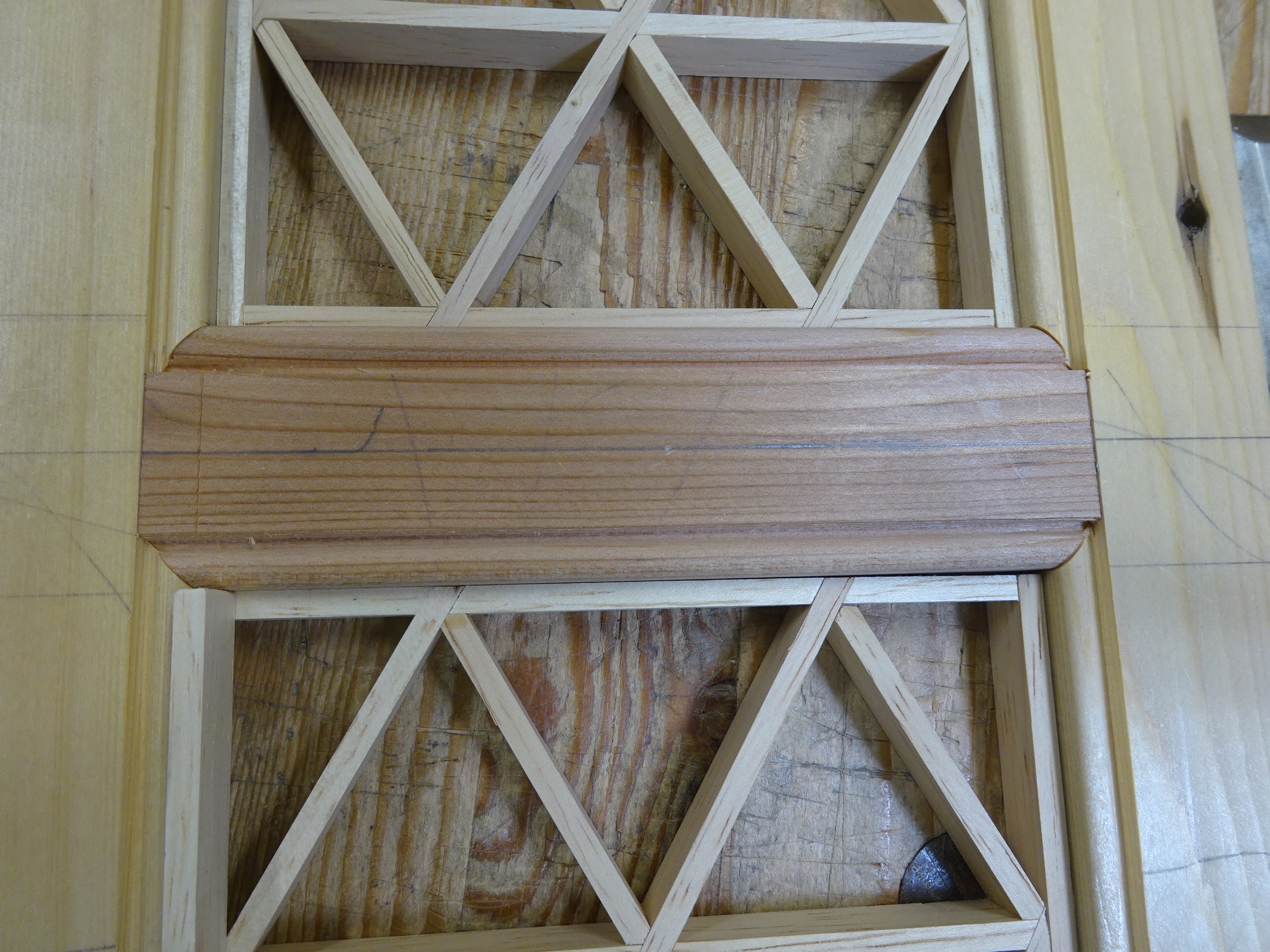
After centering on the rail, I could mark knife lines on the rail at the exact extremes of the kumiko.  I transferred those lines to the other two rails, but I'm only doing the joinery for the center rail first. When the joints were complete (making an "H" frame), I could place the kumiko panels in the openings and find out where to mark the stiles for the vertical extents of the kumiko.

Kumiko in place to find location of the upper and lower rails on the stiles

But there was a trick to that.  The top and bottom kumiko strips (that will be against the rails), bent a little outside of the two three-way joints and they didn't give an accurate total length for the kumiko.  So I made the border strips the length of the kumiko at the vertical center of the kumiko - that area was supported by the two three-way joints either side of center and this gave me a much better measurement for the border strips.

Here's how the center rail will look

I could then use those border strip to mark the stile for lower extent of the upper rails, use the rail itself to mark the upper extent of the rail on the stile, and cut the joints.  It worked very well.

And this was all just prototyping!  When it came time for the real thing I was ready.  I made no mistakes in marking or executing the joints and it looked great.

The real thing gluing up.  These clamps were not strong enough - I used better ones

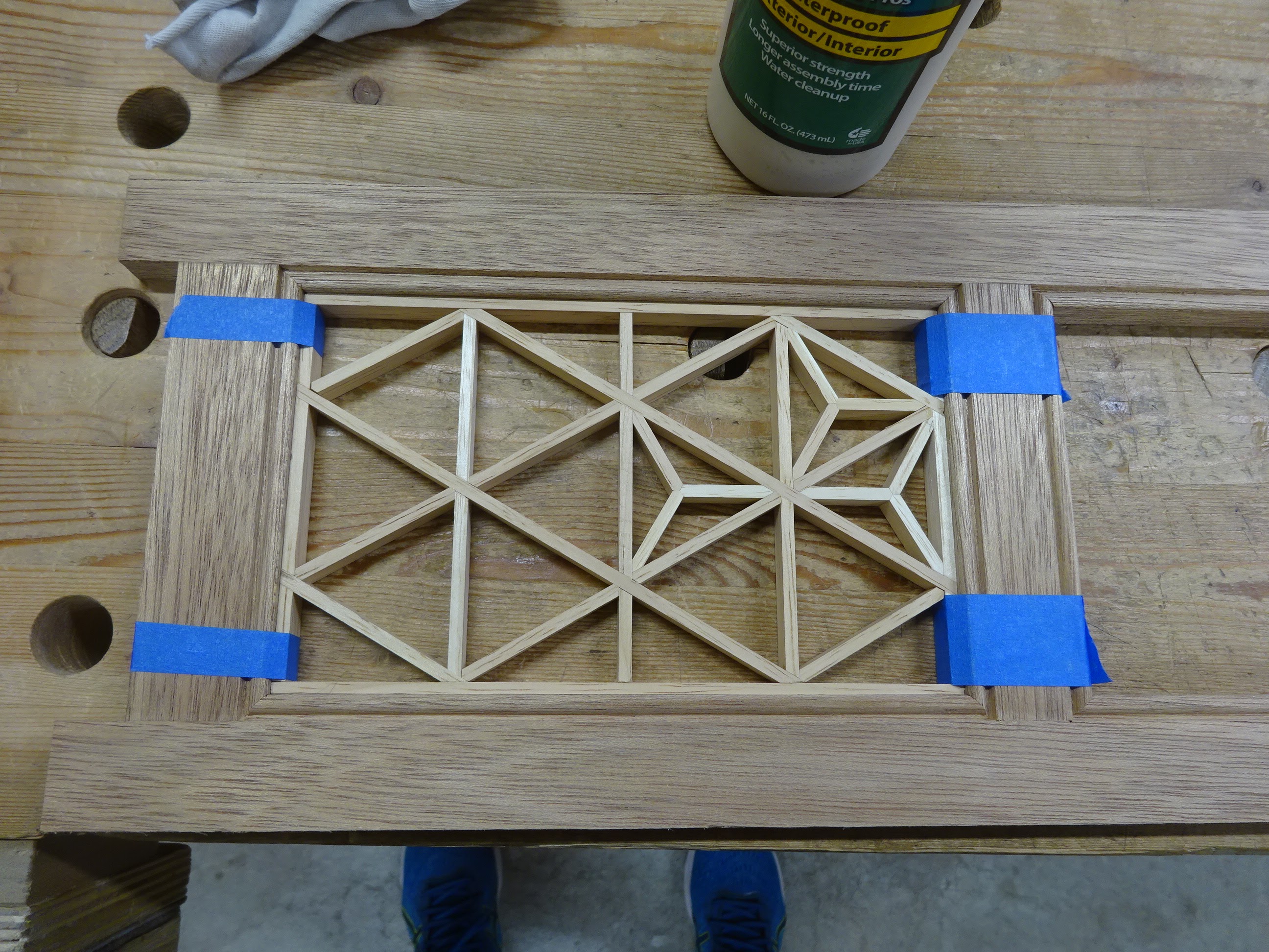
Note that the stiles have extra wood at top and bottom.  These "horns" enabled me to make a closed-in lap joint.  The horns will be cut off later when I get the door to final dimension.

After the door frame was glued up and dry, I glued in the kumiko panels.  For one of them, the side strips needed a little planing to get them to fit.  Then I started filling in the small pieces that would go in each triangle.

First panel glued in: the tape is clamping the areas that bent a little.
Also here, starting to fill in the small pieces.

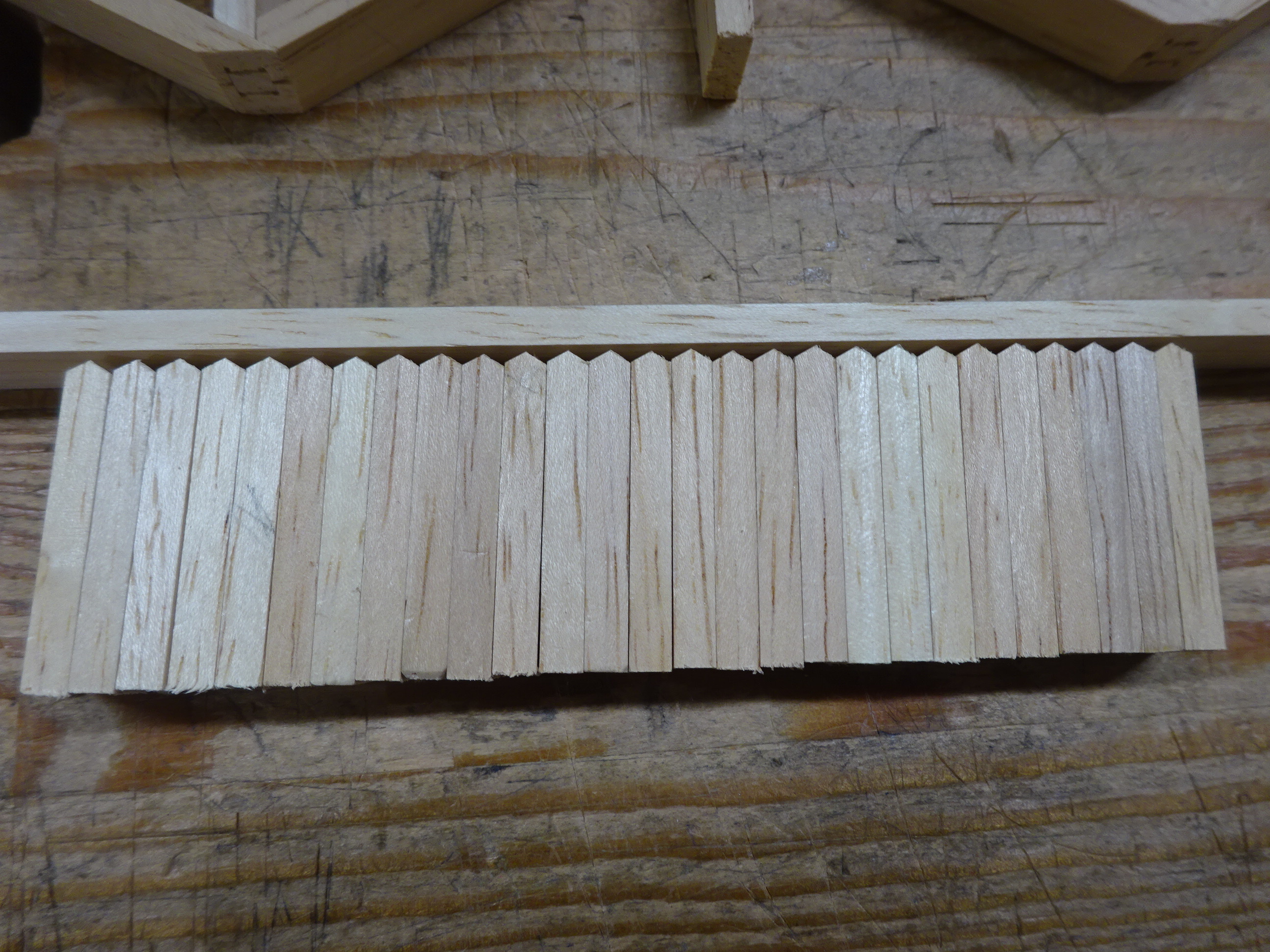
Here are 27 of the small pieces with one end formed.  I needed 72 total.

Fitting the small pieces is tedious, but enjoyable work.  I glued in the three pieces that filled a triangle when they were trimmed, before working on the next three.

Here's the kumiko complete

The project was going along so nicely.  I was almost done with mortising for the hinges when disaster struck.  When chopping straight down at the back wall of the final hinge mortise, The wood blew out!  And I had thought earlier that I should back up the wood when doing those mortises just so this wouldn't happen.  But when it came time, I plumb forgot.  Rrrrrrr.

Not easy to see, but a red line circles the area that broke out.  Here I'm gluing it back on.

Fortunately it's not very noticeable.  After adding a door pull, I put on three coats of shellac, the last coat buffed out with 0000 steel wool, and finally a coat of wax.

Glamour shot #1

Glamour shot #2

I'm very happy with this.  I had been wanting to put kumiko in a project.  It was certainly challenging, but fun at the same time.  Learned a lot.

Thursday, August 18, 2022

New TP Cabinet w/ Kumiko Door

A few years back, I made a thin cabinet for our bathroom that housed four rolls of TP.  The cabinet hangs on a thin section of the wall in our potty room (a small separate room for the toilet).  When the door is open, the cabinet is hidden behind the door.  Anyway, the TP industry saw fit to sell only mega rolls - we can't get normal sized rolls anymore (grrr) - and they don't fit in the old cabinet.  So ...

I thought I'd try to make this project with my homemade wooden planes.  And it worked out pretty well, but I did forget one time and used a #4 on something.  Old habits die hard.  I do normally use the wooden jack a lot and the new scrub has proven to be great.  But the try plane and smoother don't get as much use.

Try, jack, scrub and smoothing planes

The carcase was simple: two sides that fit into stopped dadoes in the top and bottom, and all parts get a small rabbet along the back inside edge to house a plywood back.

Top and bottom in foreground, two sides at rear

Dry fit front view

Dry fit with the back panel ready to go in place

The top and bottom will get roundovers on front and side edges.  There is room at the front to fit an overlay door and still have the top and bottom extend a half inch or so.  The old cabinet has an inset door that can only open a little more than 90° and that reduces the access of the interior by the thickness of the door (1/2").

The carcase went together easily.  But I wanted to do something different for the door.  A few months ago I experimented with kumiko and I thought I'd try to incorporate some pattern in the door.  This complicated the design and manufacture of the door by a factor of 100.  But I noodled about it for a long time and made a couple prototypes and it finally worked out.  Laying out the various cuts for the frame parts was the toughest part.

Here's something like I was thinking

The door is made up of two stiles and three rails.  Two kumiko "panels" fill the openings.  I was limited in the widths of the stiles and rails by the size of kumiko that I am currently set up to make.  To make it more complicated, I wanted to put a bead on the inside edge of each stile and rail to really outline and accentuate the kumiko.

Closeup of the left joint of the mid-rail to show the bead details

The picture above doesn't show it (because I don't know how to do it in Sketchup), but the stiles and rails will be mitered together to have the beads flow all around the panel openings.  And this complicates things even more.

Here is my first prototype joint.

Rail just butted up against the stile

Using a 45° mitering jig to make the rail fit into the stile

It takes a few tries to sneak up on the fit

Nice, but not so good for a strong glue joint

So I decided to add a lap joint

But getting the length of the parts right was a challenge

That's just one joint.  The real challenge was getting the distance between stiles and the distance between rails just right so that the kumiko would fit in the opening properly.  I think I'll leave that for another post.  It was intense (for me, maybe not for people who do this more often), but it felt good to figure it out.

Thursday, August 11, 2022

Calculating Radius of a Cambered Iron

So you want to add a camber to a plane iron and don't happen to have a round object with the curvature you're looking for.  In this post, I'll use geometry to figure out the radius so you can draw the arc with a compass.  I know, for some people I'm overcomplicating this, but for this analytically minded woodworker, it works.

This came up for me last week when I did some maintenance on a wooden jack plane.  After sharpening many, many times, the curvature of the iron wasn't as it should have been, so I set it right.  I needed to figure out the radius of curvature that would give me a 1/16" bulge on an iron that was 2 3/16" wide.  By the "bulge", I mean the amount the camber extends further than the corners of the iron.

For this blog post, I'll simplify the math by using a 2" iron width.

Artist's rendition of a 2" wide plane iron with 1/16" bulge

Closeup of the business end

I've labeled two points on this picture: Y is the right corner of the iron and Z is the point at the center of the iron directly over from Y.  The "bulge" is 1/16", the amount past Z that the iron extends.

In the next pic, I've drawn a circle whose curvature matches the camber of the iron.  The point labelled X is the center of the circle.  Also drawn is a line from X to Y, and since Y is on the circle, segment XY is a radius of the circle.

Circle drawn that matches curvature of the camber

Zooming in again, we see a triangle formed by XYZ.

Triangle XYZ

We have enough information now to calculate the radius of the circle, and from that, we can draw a template of the camber to be transferred to the iron to guide grinding and sharpening.

Triangle XYZ is a right triangle.  The Pythagorean theorem tells us that YZ^2 + ZX^2 = XY^2.  (Read "^2" as "squared".)

XY is the radius of the circle: I'll call it R.

YZ is half the width of the iron, in this example 1".

ZX is slightly less than a radius, by 1/16", so ZX = R-(1/16).

So we get:   1^2 + (R - 1/16)^2 = R^2

Simplifying: 1 + R^2 - (1/16) R - (1/16) R + (1/16)^2 = R^2

Simplifying: 1 -(1/8) R + (1/256) = 0

Simplifying: 1+(1/256) = (1/8) R

And finally: R = 8 * (1 + 1/256) = 8  1/32"


In the case of my jack plane, the iron is 2 3/16" wide and the calculation came out to give a radius R =  9.6" ( I rounded to 9 5/8").


If one wanted to extend this to any bulge (call it B) and any width iron (call it W), then the formula comes down to:

R = ((W/2)^2 + B^2)/2B

I know this is not for everybody.  In fact, it's probably a lot easier to simply draw an arc using a nail, a string and a pencil, changing the string length until you get the right bulge on the arc.  But I like the analytical approach.  Math has served me so well over the years.