Thursday, June 30, 2022

Benchtop Shave Horse (Pony)

Oh, how I wish for more space.  It'd be great to have a full size shaving horse, but I just don't need one badly enough to justify the space it would take up.  I've been thinking about it a long time and finally decided to do something as a substitute.  The internet shows folding shave horses, bench-mounted shave ponies, vise-mounted shave ponies and other devices you can build that are space-saving solutions.  Here's what I came up with.
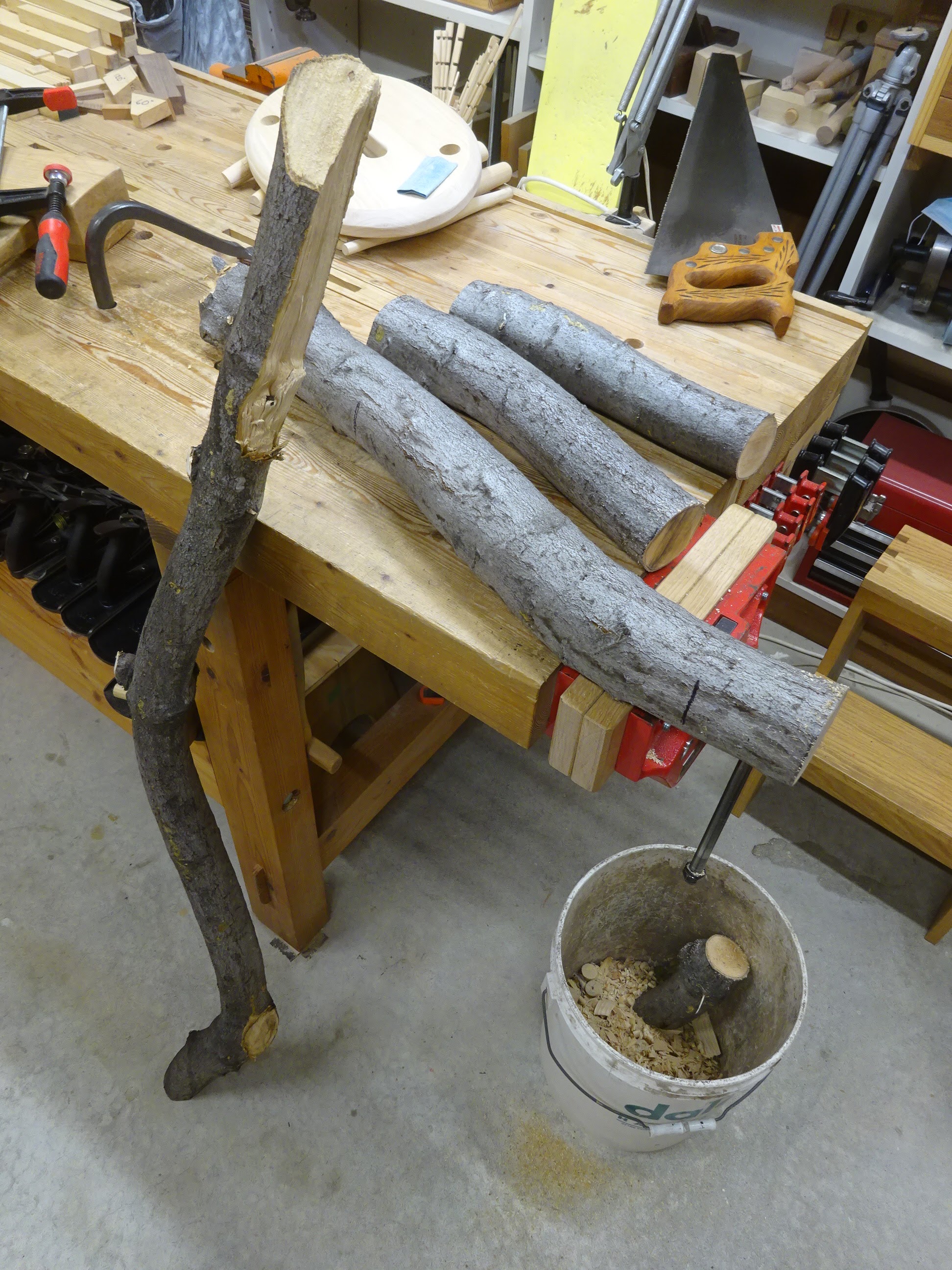
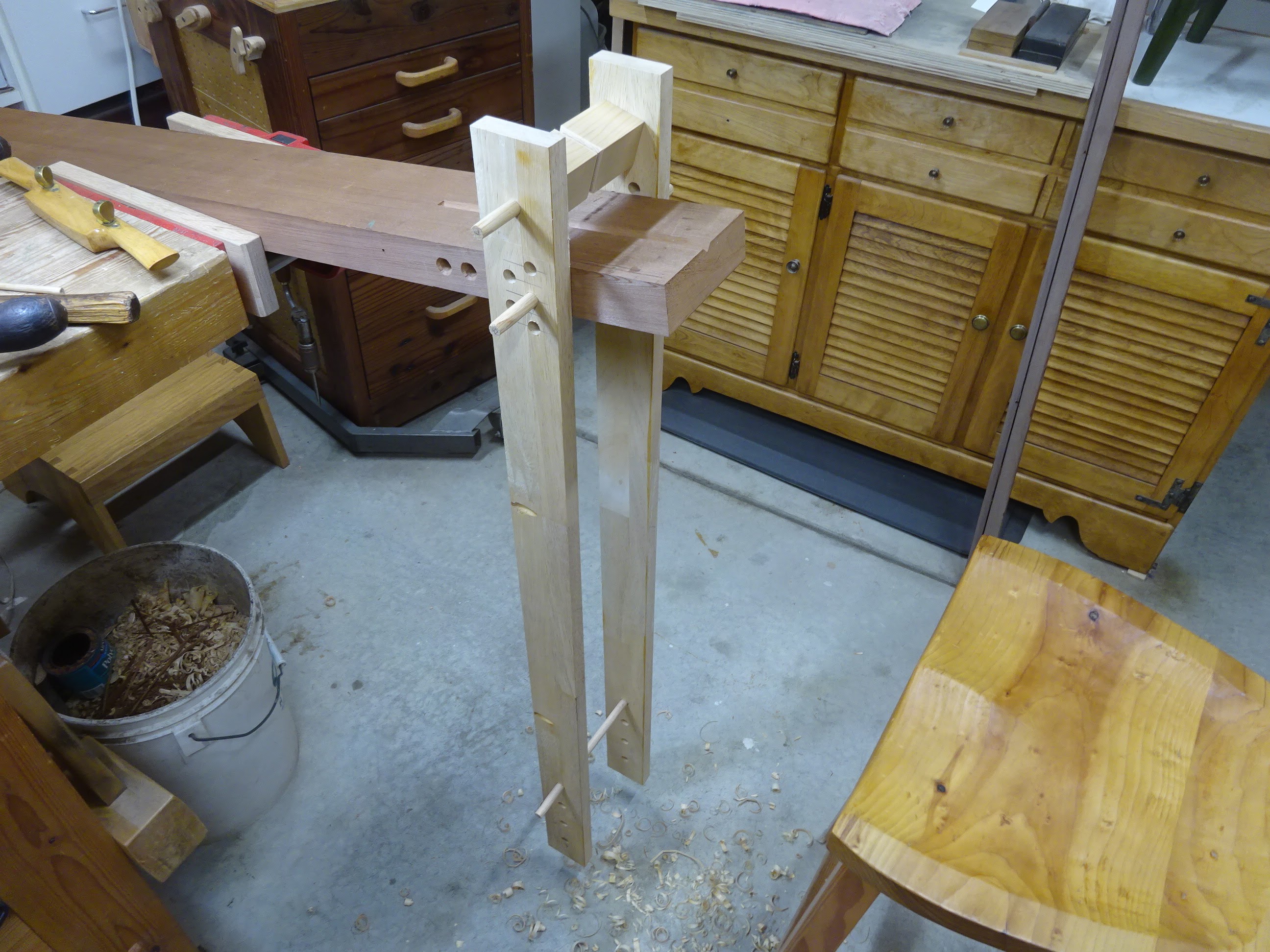
Here's the setup

It's basically a chunk of wood (the base) clamped in a bench vise, with a clamping frame that pivots via dowels through the base to put pressure on a workpiece when the foot treadle is pushed forward.

There were a lot of considerations with this.  If I mounted it in my tail vise (as shown above), the bench would get pulled out of position.  Even though my bench is pretty heavy, it'll still move when yanking on wood with a drawknife.  So if it was to be vise-mounted, it would be better to have it in the front vise.  I can still do that, but will probably use it in the tail vise due to space limitations to the left of my front vise.

At first, I thought it might be nice to have the option to stand or sit when using it.  But I can tell already that it is far more comfortable when sitting.  The nice thing about mounting it in a vise is that I can angle the base as needed to accommodate a comfortable drawknife pull stroke.

Then there's things like the length and front-to-back location of the treadle frame.  I decided to make it long and adjustable.  Even after just a short time using it, some of these considerations are fleshing themselves out.

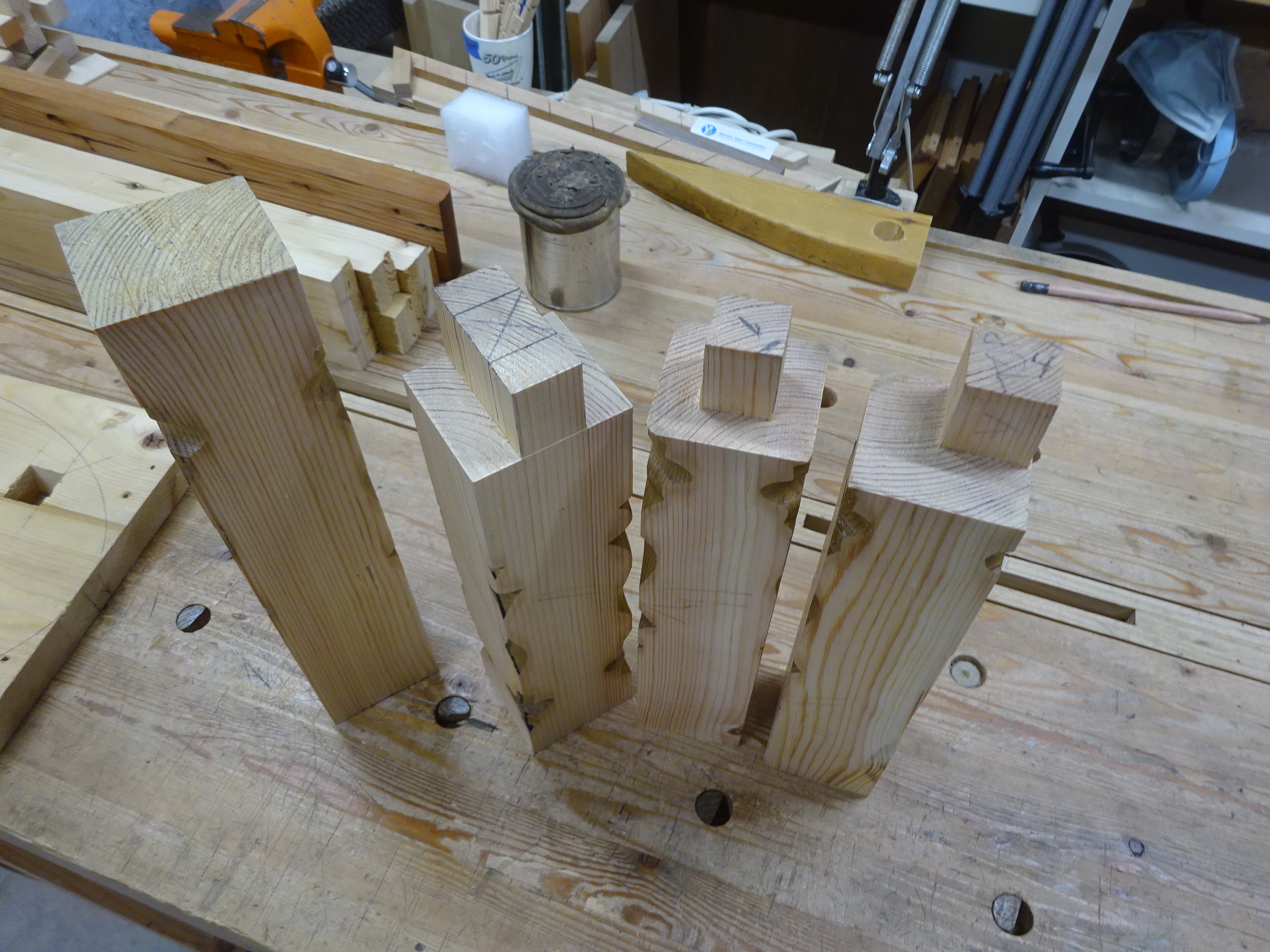
Here's how it was made - all scrap wood as usual.  The base is a chunk of 5" wide, 1 5/8" thick redwood, originally 50" long that I eventually cut down to 25".  This could probably have been just 18".  This piece clamps into a vise.  Starting about 3"-4" from the front end, I bored 5 holes at 1" intervals through the width of the board.

Base board with guide lines on top, three holes bored through so far

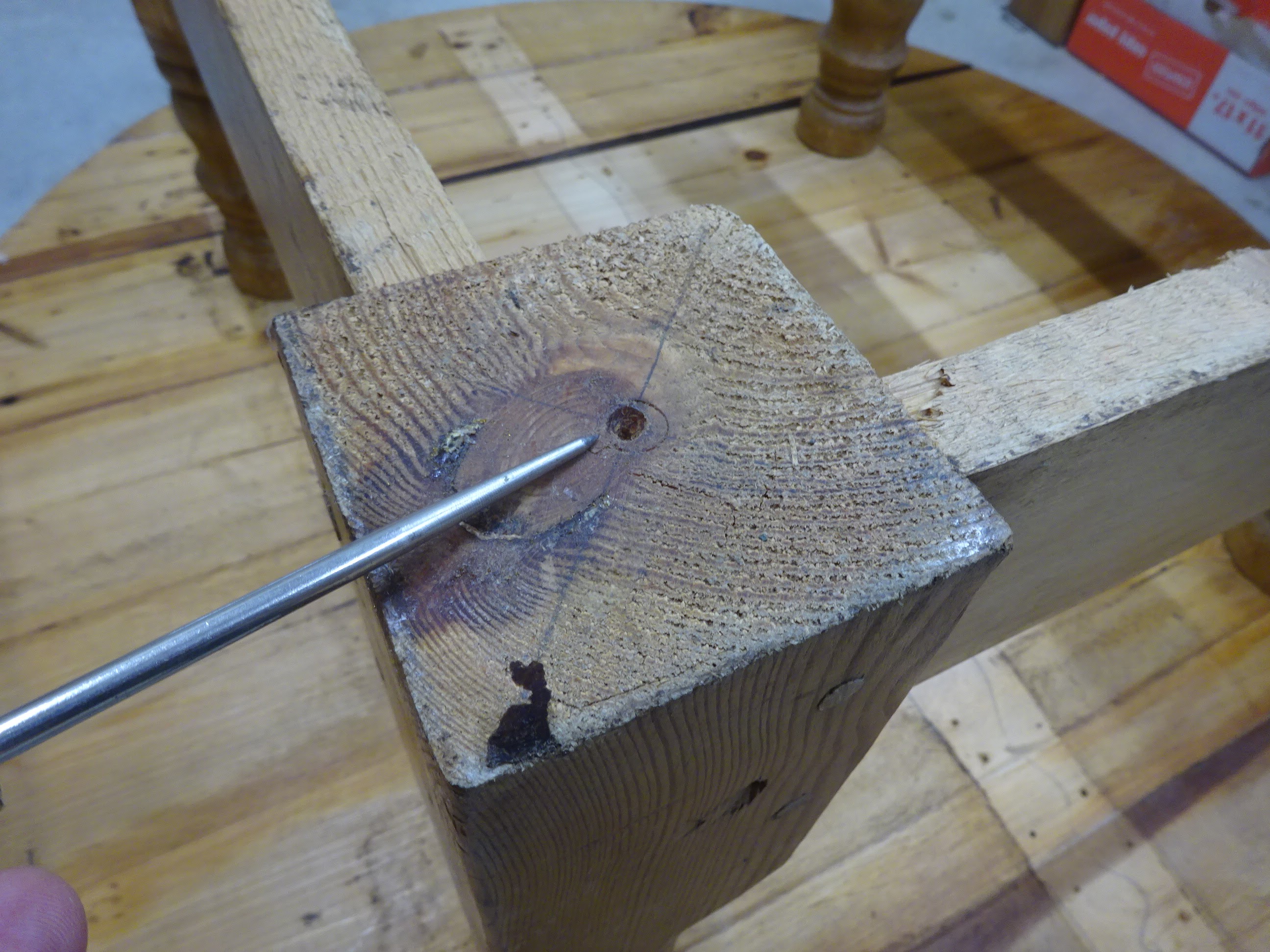
Boring straight through for 5" is a challenge, so I used a straight-ish piece
of wood as a guide, set along a pencil layout line.  Here, I'm lining up the auger bit
with the edge of the stick of wood for lateral alignment.

For the vertical alignment, I placed a mirror a few feet to my right
and tried to see if the auger bit was parallel to the stick of wood.

Here's a close-up of the mirror - see the auger bit? - looks like I'm aiming a bit high
(the clamps are holding the base to my workbench)

After boring more than half-way, I flipped the board and came the rest of the way from the other side.  The 7/16" holes weren't perfectly straight, but good enough.  I did have to shave down the 7/16" oak dowels that I made to slide through there a bit easier.

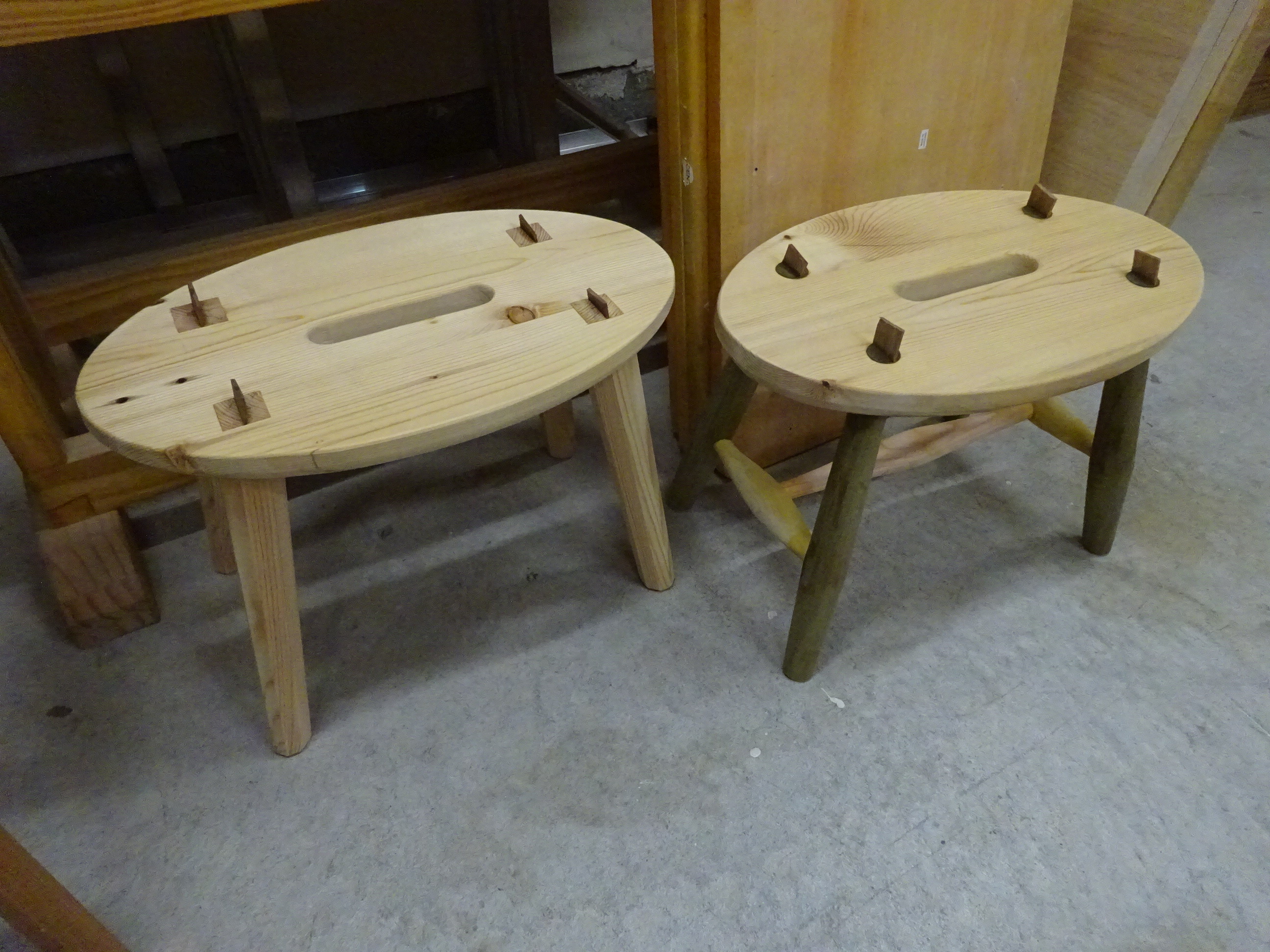
The clamping mechanism is like on English shave horses, with uprights that straddle the base.  There are 5 holes to adjust the position of the pivot point for when working on thicker or thinner stock.  Above those holes is a single hole, through which a dowel fits that holds the clamping block.

You can see the adjustment holes for the pivot point as well as for the treadle

Chiseled a V-shaped groove in the base as well as in the clamping block for
 holding a piece in a "diamond" shape when working on corners of a blank.

I eased the corners of these V grooves, though the base is soft redwood and the clamping block is soft pine, so there's little chance of ever marring a workpiece on the edge of a V groove.

After getting a little practice using thicker and thinner stock, it became a drag to pull out the pivot pin and raise or lower the clamping frame.  So I found that setting it up for thicker stock and putting in a wedge-shaped piece of wood to raise up a thin workpiece worked great.  It doesn't even have to be wedge-shaped - it could be flat.  It just needs to raise the workpiece up a little.

Wedge-shaped shim used to raise the workpiece so clamping is a breeze

There are two more points of adjustability.  First, there are five holes in the base for the pivot pin.  I found the hole furthest forward to be best - it was better to clamp the workpiece close to the front end of the base.  Second, the clamping bar is about 1.5" square.  The hole through which the dowel extends is offset from center so that it is centered 9/16" from one face, 11/16" from another face, 13/16" from the third face and 15/16" from the fourth face.  By rotating the clamp bar, you get as much as 3/8" of adjustability for different sized workpieces.

One thing about this design: the clamping frame is far taller than on a traditional shave horse.  This allows you to get tremendous leverage on a workpiece - it holds like crazy.  But if it's not set up just right, you have to extend your foot farther than is comfortable to actuate the clamp.  I put the treadle bar - which is just another 7/16" dowel - at the highest hole setting that I bored.  I may end up cutting these uprights a little shorter.  And I might also attach a piece of wood near the bottom of the uprights that extends forward (towards my foot).

Some final touches included making knobs for the dowels so they're easier to remove and insert, and rounding over the tops of the uprights, which adds comfort and gives a little more room to fit a drawknife when the clamp is engaged.

Knobs for the dowels, round-over on the uprights

And this job's a good'n.  Now if I could just get some straight-grained green wood out here in CA.  Hopefully more on that to come.

Thursday, June 23, 2022

Pittosporum Spoons?

I've done a fair amount of reading about working with green wood, but don't generally have access to fresh-cut wood, so I have a lot of questions.  I suppose that's normal when doing something for the first time.  I took a limb of a pittosporum down the other day and thought I'd try to make some spoons.  Our pittosporum trees are evergreen, about 25 feet tall, with trunks of 6-8" diameter.

I know nothing about the wood of the pittosporum.  An internet search was fruitless.  No idea if the wood is good for anything other than holding the tree upright.  Is it toxic or allergenic?  Is the wood soft or hard?  Will it split nicely and is it workable with hand tools?

The limb I took down was only about 3-4" in diameter.  Seems like people usually start with far larger blanks when making spoons.  But it's what I have, so I'll see what I can do.

Cutting into useful sized pieces using a 26" handsaw that usually cuts dry wood.
It was helpful to keep the saw plate lubricated with oil.

Before working on the spoon blanks, I thought I'd try splitting a small off-cut first.  So I got out my high-tech splitting equipment and to my delight, it split very nicely.

Hatchet, rubber mallet and 2" thick poplar "chopping block"

A small piece of pittosporum split

So I split the first three pieces from the larger section of the limb - this went OK, but it wasn't as easy because there were some knots and irregularities to contend with.  Then I removed the bark with the hatchet - it came off easily.  I was interested in seeing how a drawknife would cut in this fresh-cut wood, so I did some initial shaping with that.  The wood peeled away with ease!  I see now why green woodworkers love drawknife work on their wood.

Rough shaping the handle with a drawknife

Before going too far, I drew a spoon shape on the wood, then removed more wood to get closer to the lines.

Rough layout - just making it up as I go along

Three future spoons or dumpster fodder - time will tell

I also used the hatchet to do rough shaping, using techniques I've read about and seen in videos.  It worked pretty well, but in the position below, my back was arguing after a short while.  Maybe if I had a real chopping block (and room to keep one), it would be more ergonomic.

All for now.  I have 6 spoon blanks roughed out and will let them dry for a few weeks.  No idea where this will lead, but at least it's fun to learn something new.

Oh, and if anybody out there knows anything about pittosporum wood, please leave a comment.

Friday, June 17, 2022

Nice Save!

Here's what happened when I was tapering the mortises in the top of a step stool.  The old recycled pine was soft enough that my tapered reamer really chewed up one of the holes.  Three of them were OK, but one was so horribly disfigured that I thought I might have to scrap the top altogether and start anew.  The hole was no longer even close to the proper angle and the edges were chewed up.

This first stool came out fine; it's the other one that is the subject of this post

The platform of the stool in question - underside shown

These mortises started out round.  While tapering them, the lower left mortise went for a drive to la la land (sounds like I've been reading Ralph's blog too long).  I thought about it for a while and decided I'd try to save it.  The holes were bored at 3/4" diameter and when tapered, the bottom side was closer to 15/16".  I decided to make square mortises and tenons, about 1" on a side.  The lower left mortise I had to make about 1/ 1/8" square because the edges were so gnarly.  You can see some nasty edges in the above pic even after chopping the large, square mortise.  While chopping the mortises, the first three mortises were at approximately the proper angle, but to make the fourth at the proper angle, I'd have had to make it much larger.  So I didn't even try to make the fourth at the proper angle; it was still way off the mark.

Some of the tenons being formed.  These legs started out way
oversized, which allowed me to save this project.
(note: leg #4 at right has its tenon in a corner to allow shaping the leg at an angle)

After fitting the tenons to the mortises.  I turned the stool upside down and put the first stool right-side-up on the upturned feet of the second stool.  This allowed me to find out where the feet of the second stool should be.

Setting a stool with properly spaced feet on upturned second stool

Marking the feet locations on bottom of stool #2 feet

Here's the bad leg - note how far off-center the foot will be once material is removed

Marking the leg shape on the fourth leg
(most of the turned areas you can see from its former life were removed in shaping)

My leg blanks were far beefier than I needed and that saved this project.  I could shape the fourth leg in such a way as to make it end up at the proper angle.  I made the legs octagonal, tapering from 1 3/8" where they meet the top to about 1" at the feet.

Saved!  Glued up and cooking with wedged tenons

The moral of the story is: you can usually save a project - especially if it's not "fine woodworking".  You just have to think about it a while, weigh the options and perhaps try something new.  Not sure if I've made angled square mortises before, but these came out great.

Thursday, June 2, 2022

Anatomy of an Old Pine Table

This table showed up on Freecycle dot org, and I'm just a sucker for free wood.  It's definitely not "fine furniture" and probably falls in the category of "country furniture".  The lady giving it away said she got it some years ago from an antique furniture place.  At first I thought it was probably just a reproduction, but after taking it apart I can see it was the real thing.  Originally it was the appropriate height for a dinner table, but a few years back they cut down the legs to use it as a coffee table.

About 48"diameter, knotty pine top (not close to flat or smooth)

Turned legs had been cut down.
Aprons with a large bead detail at bottom.

It was made from a very knotty pine, with a 48" diameter, 1 1/8" thick top that, when looked at from a very low angle, wasn't close to flat.  There were two battens screwed to the underside of the top at the widest cross-grain location.  A cutout was made in two aprons to allow for the battens.  Oddly, near the outside of the table, the battens were affixed to the top with four relatively new and small (#8?) Philips-head screws.  Further towards the inside, they were affixed to the top with big, old slotted-head screws through elongated holes.  No glue was used with the battens.  I don't know why the new screws were there.

The table belly-up; note the battens

Batten with some new and old screws

The undercarriage comprised four beefy legs and four beefy aprons.  The legs were just shy of 3 3/4" square and were turned below the level of the apron mortises.  The aprons were 1" thick (one of them was 1 1/8" thick), 4 7/8" wide and 23 1/16" long, including the 1 7/8" long tenons.  The inside of the aprons had a groove plowed near the top for buttons that were used to affix the top.

Two of the 9 buttons (why not 8?), with relatively new (why?) screws

The one-cheeked tenons of the aprons were pegged (don't believe they were draw-bored) into the mortises.  One m&t joint had three pegs while all the others had two.  And the position of the pegs was anything but consistent from one m&t to the next.

Two pegs on this one

Three pegs on this one - the third one went right through the quirk and splintered the bead.
Regarding the bead, would you put your beading plane through that huge knot?!

The 5/8" bead extends onto the tenon and goes into the mortise

The aprons' tenons had a top 3/4" - 1" shoulder, which was
way more than needed since the mortises went to 5/8" from the top of the leg

The 9/16" wide, ~4 3/8" long, ~2 3/8" deep mortises were inset 5/8" from the edge of the leg and stopped about 5/8" from the top of the leg.  There was no haunch.  The mortises at first appeared to have been bored out with a brace and bit before having the walls pared.  But after further investigation, I now think that these mortises were made using a mortising machine with hollow chisel.  To look at the mortises, I split a 5/8" thick chunk off the legs.  The removed chunks slid easily over the pegs.

Splitting off 5/8" of the leg to get at the mortise

Look at all that extra space in this mortise!
And check out how the bead extends to the end of the tenon!

The mortise wall of a split-off section

The inside mortise wall - note the circular patterns at bottom.
Another detail: the dowels were 3/8" diameter and shaped with ridges.

The circular indents at the bottom of the mortises at first made me think these mortises were bored out with brace and bit.  But two things indicate they might have used a hollow-chisel mortising machine.  First, there are no thread indentations where the lead screw would have pulled an auger bit into the mortise.  Second, the mortise walls are too straight, with no indication of rounded areas (from an auger bit).  It appears as if a hollow chisel was slightly out of parallel with the leg, leading to obvious vertical lines, but also that the chisel wasn't sharp, leading to the horribly rough mortise walls.

Here are a few more random details.

Machine marks on bottom edge of apron - was a jointer used?
Also, if a beading plane was used, it wasn't adjusted quite right
as evidenced by the step where the bead meets the apron's edge.

This apron show surface was far from flat - was it ever?  Who knows?

The inside face of this apron shows no attempt at surface planing

Each leg had its center marked with intersecting diagonals and
the turning center was clearly visible 

An interesting table, to be sure.  It was made in a utilitarian fashion.  The mortises were made quickly and oversized with no extra work to true them up.  The aprons were planed only on show surfaces (if at all).  Machine marks show on inner faces and edges.  The beads were done rapidly with little care about tearout.