Wednesday, October 26, 2016

Nana's Dining Chair Rebuild, Part 3: Joinery Layout and Making Templates

Well, the week in Utah was great.  Over the course of five days I hikes about 43 miles, mostly in Canyonlands National Park.  What a place!  Don't tell anyone (lest it get overcrowded), but the "Needles" area in the southern part of the park is so beautiful.  Fall is probably the most popular time for this park, but I only saw a few other people once I was a mile or two from the trailheads.
View of Needles District of Canyonlands NP
I got back to the project this week.  I did most of the grunt work of stock prep on Monday and Tuesday and man, am I sore!  Today I spent making templates and very carefully marking out some joinery.
Front leg template, copied from original
Before cutting out the back leg template I drew a straight line (red dotted line) that I'll use to get a flat spot for the lower rail joinery.  The plan is to cut off the waste and plane it to the red dotted line, lay out the joint and then fair the rest of the curve (leaving a little flat spot for the joint).  This layout also gives me one of the angles I'll need when cutting the shoulders of the lower side rail.
Lower portion of rear leg
I also drew the line on the leg blanks and I'll cut and plane to the lines.
Cut lines drawn on rear leg blank
It really helps having the original chair to make templates from.
Template for lower backrest rail
Just a couple more pieces to make templates for.  Shown below are both aspects of the back leg, the front leg template and the lower backrest rail.
Bunch-O-Templates
On a side note, look at the lower aspect of the lower backrest rail.
Bottom of the lower backrest rail
It's very rough - looks like bandsaw marks.  I can understand why the maker may not have wanted to smooth this up (because it's rarely, if ever seen), but that's where I might grab the chair to pick it up, so I'm going to make this easier on the hand and smooth it up on my version.

Laying out the joinery was slow going.  I was being so careful to mark on the correct faces, at the correct locations.  The front leg upper rail mortises were pretty straight forward.  Note in the picture that I have an extra inch or so above the top of the leg so that when I chop the mortise I won't blow out the top of the leg.  For door stiles they call this extra length a "horn" and that's what I've called it here.  I'll cut it off later so the top of the front legs will be flush with the top of the rails.
Front leg upper rail mortises marked out
In the above picture the front leg is resting on the lower legs, overhanging at the bottom by 1/2".  In a fully assembled chair, when the seat rails are parallel to the floor the front legs extend 1/2" lower than the back legs, providing a bit of backward lean when all four legs are touching the floor.  Anyway, the side rail joinery lines were transferred to the back legs directly from the front leg layout.
A closer view
After some calculations I drew in the rails and tenons.  Notice how the tenons (the smaller rectangles inside the larger ones) are offset for the side and back rails where they meet the back leg.
Side rail (top) and back rail (lower) drawn on back leg.  Notice offset tenons.
I'm going to wait to lay out the joinery for the backrest rails until I've removed some of the waste and created a flat surface to reference from.

I've put a lot of thought into the order of cutting the shapes and cutting the joinery.  I sure hope I'm not missing something.

Finally for this post, this chair has a lot of angles to deal with, primarily on the shoulders of the upper and lower seat rails.  Problem is, I only have one bevel gauge.  So I worked out most of the angles and marked them on a piece of poster cardboard.
Several of the angles I'll need to replicate
This way I should be able to reset the bevel gauge as needed.  It's not ideal, but until I get five more bevel gauges, it'll have to do.

Next up is my favorite part: cutting and fitting joinery.  Can't wait!

Saturday, October 8, 2016

Nana's Dining Chair Rebuild, Part 2: Some Joinery and Build Considerations

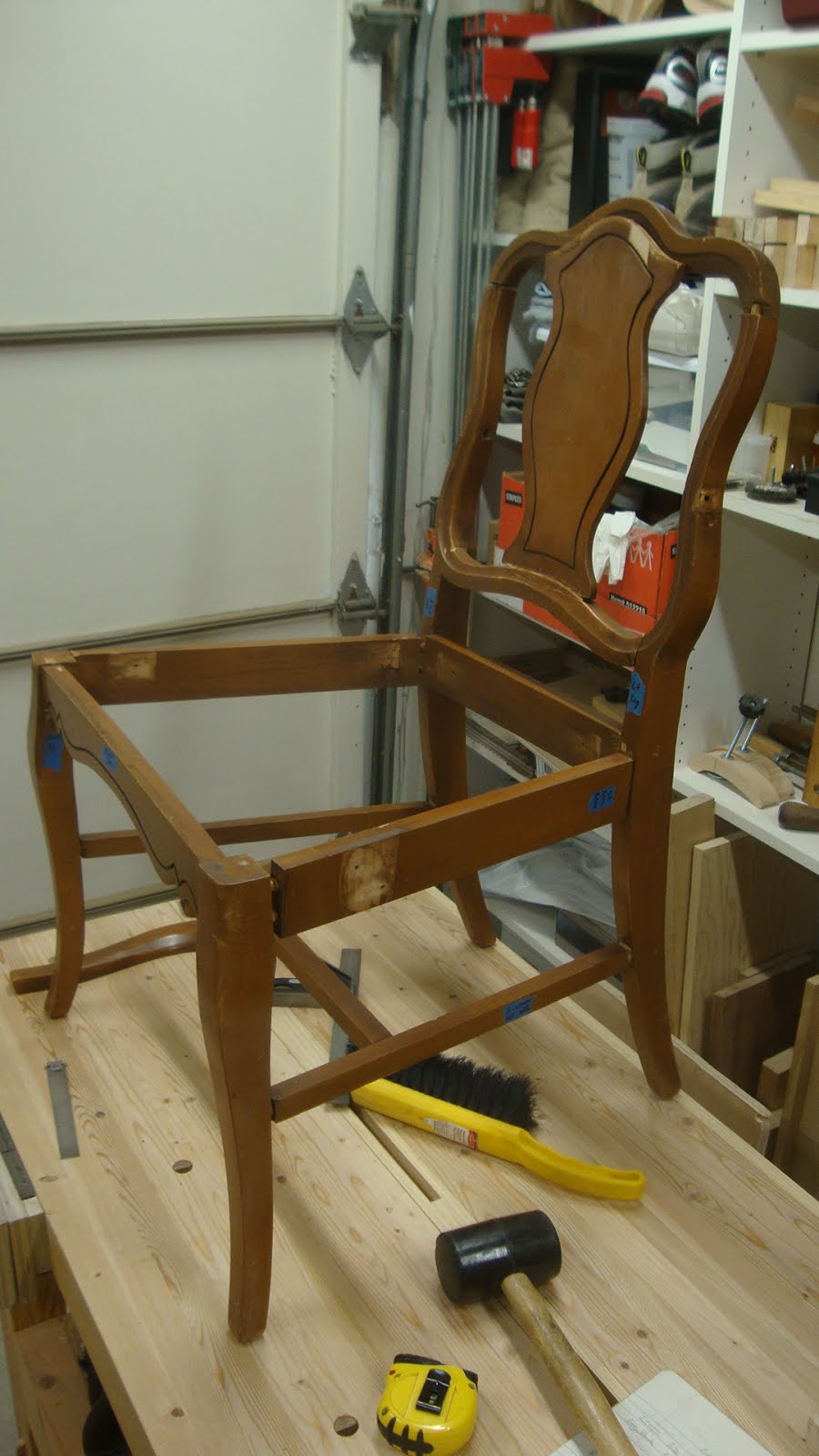
The chair I'm duplicating was the "head chair" (for lack of a better term) of the set of six and differed from the rest in that it had arms.  I got one of the other chairs out of storage to get more information on layout and joinery details.
"Head chair" at left (arms are not currently installed) and one of the others
It turns out that there are more differences between these chairs than just having or not having arms.  The head chair's front seat rail and side seat rails are about an inch longer than those for the armless version.  And the same applies for the lower rails.

I used the second chair to check out the backward lean of the chair.  It turns out that if I put a 1/2" shim under the back legs ...
Shim under back leg
... I get the seat rails parallel to the floor.
Seat leveled with 1/2" shim under back legs
This is important in the layout of the mortises in front and back legs.  In the drawings that follow, the bottoms of the front legs are set down 1/2" lower than those of the back legs.

I'll get to the drawings in a minute.  I'm not certain what wood was used for these chairs.  I scraped some finish off of one of the back legs to see the wood.
Not sure what wood this is
Another area of that leg showed definite evidence of poplar.  The curves on the upper leg required wider stock and you can see that a piece was glued on to provide the extra width.
The greenish wood is most likely poplar
I'm going to use poplar for this project, but I'm going to make the the back legs from a single piece.  You can see where a crack had formed in the above picture.  I hope the use of a single piece of wood will make it stronger.

Before I made the Sellers dining chairs I bought a flip chart like those used in businesses for presentations or meeting.  While expensive (over $30!), it has been nice to have paper this size for full scale drawings.  It's got vertical and horizontal lines at 1" spacing.  This first drawing is a cross section through the seat rails and legs at seat height.
Seat rail layout with legs
I hope you can see enough when you make the photo larger.  It is really invaluable to make full scale drawings to play with joinery.  Here's a closeup of the lower right corner of the above picture.
Front left leg joinery detail
==========================================================
Gotta stop to ask a question of anyone good enough to respond: do you name the left and right parts of a chair (or table, or cabinet, etc.) from the perspective of someone looking at it from in front of it?  Or do you name the sides from the perspective of someone sitting in the chair?  For example, sitting in the chair, my right leg would be near the right leg of the chair.  That's how I'm naming it.
==========================================================

In the above picture, some of the leg blank with be cut away during shaping.  In the picture above, the bit at the right and bottom will be cut away - that's why the reveal is measured from the dotted line.  To maximize the tenon length I show them mitered.

The rear leg joinery is much more interesting.  Remember the original chair was doweled together.  If I try to use M&T, I run into crossing tenons.
Rear left leg joinery detail
This shows why the original builder did something that I thought was interesting.  Here is a picture of the rear right leg, rear seat rail (to the right in the picture) and right side seat rail (coming toward the camera).  You can see that the the rear rail is higher then the side rail by about 1/2".
Right rear leg and seat rail joinery
This was so they could use dowels without the dowels for the rear rail intersecting with the dowels for the side rail.
Rear leg showing offset dowel holes
Here's how I'm going to handle it with M&T joints.  The following picture is a side view of the chair.  The red lines show the tenon of the side rail.  The rectangle that the tenon intersects is the rear seat rail (end view) and its tenon is shown in pencil dotted line.
Side view of chair
  My two tenons will not extend the usual width of a tenon.  I'm also going to make my short shoulders just 1/8" to add a little tenon width.  Here's a close-up photo.
Close-up of side view of rear leg and seat rail joints
I'll still get 1 1/4" width tenons (rather than the 1 3/4" I normally would have gotten) and they will not interfere with each other.

Another area that will be tricky is the lower rails, which will be joined to the front and rear legs in areas where the legs have a curved shape.  Here's the back leg / lower rail detail.
Back leg to lower rail joint
I'm planning to first plane a flat section (see the slanted dotted line) tangent to the curve at the joint location.  After the joint has been cut and fitted, I'll complete the shaping, leaving a small flat where the joint is.

The front leg is a different story.
Front leg to lower rail joinery

It would be tough to plane a flat spot at the location of the joint.  I think I'll just use the full scale drawing to determine the angle to use for the vertical shoulder of that rail.  This should be a real challenge.

It's really interesting how just a bit of experience has made me think of these things BEFORE I start cutting.  A great lesson to learn!

Finally, I got the wood for the project: some 5/4 poplar for rails, arms and backrest and some 8/4 poplar for the legs.  Mini rant: I can't seem to get full 4/4 wood from the local hardwood dealer.  It's planed to about 7/8" and I need 7/8" for my final thickness.  I was luck they had 5/4 thickness.  Arrgh!
Poplar for the project
I've already started cutting rough blanks for the project pieces.  The front legs, all rails and backrest pieces are stickered.
Most parts cut to rough dimensions
Still need to cut another back leg blank and the arm pieces.  I'll do that Monday and let them sit for a week.

I'm off Tuesday to southeastern Utah for a week of R&R - probably a lot more recreation than rest.  Catch you all on the flip-flop.

Wednesday, October 5, 2016

Nana's Dining Chair Rebuild, Part 1: The Old Chair

A number of years ago my sister gave me a dining table and six chairs that had once belonged to my grandmother.  Other than the fact that they were Nana's, they are not that special - not valuable antiques or anything.  I scraped some finish off one leg and I think it was made of poplar.  I used these chairs in my old house for several years, but when I moved a few years ago they went into storage.  The chairs had been kind of rickety for many years and about 5-6 years ago I took one apart with the intent that I'd someday reproduce it.  That day is finally here.

When I disassembled the chair, I labeled all the parts.  This was fortunate since my memory isn't what it used to be.
The dining chair - all parts laid out
They've been sitting in a box, first at my old house and for the last 3.5 years in storage.
Box-O-Chair-Parts
Here is the chair partly assembled.
The chair assembled minus the arms and seat
The parts of this chair seem small in relation to the parts I used for the "Sellers" dining chairs that I built earlier this year.  The original rails are of 3/4" material and I plan to use 7/8" for the new chair.

The original was put together with dowels, but I'm planning to use M&T joints whenever possible.

I got one of the other chairs from storage today to use as a model and get some measurements from.   The front legs are 18 1/2" apart and the rear legs are about 13 1/2" apart. So, like the Sellers dining chair, the side rails are angled front to back.  There are some interesting features to this chair that will really stretch my current abilities.
Another chair fully assembled for comparison
Here is a side view of the chair showing the degree of curvature in the back.
Side view
One of the tough things to figure out about this chair is the layout of the back legs.  At seat level, there is 13 1/2" between the legs.
Back view showing distance between back legs
Closer view at right side
At the level of the lower rails, it about a 16th of an inch less.
Distance between back legs at lower rails
Closer view at right side
And at the floor, it is only about 13 3/16".
Distance between back legs at floor
Closer view
This could be explained if the side faces of the legs were slightly out of parallel with the front-back centerline of the chair.  But it also could be that the loose joints and many years of use have twisted the legs out of their original position.  In either case, it will make the construction far easier if the legs' side faces are parallel to the chair's front-back centerline.  And that's how I'm going to lay it out and build it.

Another interesting tidbit about this chair is the connection of the back leg to the side rail that supports the seat.  The back leg is curved and in the original that curve mates with a rail that has a square end.  I'll be making sure there is a nice flat portion of the leg at this location.
Not such a good connection
Here's another challenge.  The following picture is of the left side of the chair looking down from above.  You can see the upper side rail that connects the front leg to rear leg.  But closer to the floor is the lower rail connecting front leg to rear leg (see the arrow).  It's at a different angle from the upper rail.  Because of the curvature of the lower part of the rear leg, the lower rail is about an inch longer than the upper rail and that changes the angle.  That means the shoulders of the lower rail will be at a slightly different angle than those of the upper rail.  Same for the tenons.
Left side of chair viewed from above
Finally, look at the backrest.  It comprises the two rear legs (the side uprights are the upper extents of the rear legs), a lower and upper backrest rail and a captured panel.
Backrest detail
The panel will have it's own challenge when it comes to cutting the channel that is offset about a half inch from the perimeter.  In addition, the panel is captured in stopped grooves in the curved upper and lower backrest rails.
Upper part of panel set in groove in upper rail
Lower part of panel in it's groove
Closer view of the channel at lower right of panel
Now look at the joinery of the backrest.  The next picture shows the lower backrest rail joined to the upright (the rear leg).  You might be able to see that the rail is only about half the thickness of the leg at that point.  Not sure why that was, but I might match the thicknesses of the two parts.
Lower right area of backrest
The part I've been struggling with is where the upper rail joins the upright.
Upper right area of backrest
This joint, like all the others on the original chair, was joined with dowels.  I've been thinking about whether the joint would be better if the upright was longer and the upper backrest rail joined into it from the side (think "vertical" joint line instead of horizontal).  I'd like to get some feedback on this if anybody is still reading and wants to chime in.

I'm going to make this out of poplar, which I think was used on the original.  I've got to go get some wood and start getting it to size.  More later ...

Monday, October 3, 2016

A Bathroom Cabinet, Part 3: Finishing

It's been a while since the last post, but I have an excuse for some of that time.  We spent a long weekend tent camping in Yosemite National Park up at Tuolumne Meadows, which is up at about 9000' elevation.  It got into the 20's (°F) the first night which was damned chilly, but other than that it was very nice.  Did a little hiking and one day got to this beautiful location.
Shamrock Lake just outside Yosemite


Anyhoo, after returning home and recovering for a couple days I got to the finishing part of the project.  I was trying to match the color of an existing cabinet under the sink, so I tried a couple things.  Because it's in a bathroom and will hang next to the shower, I knew I needed a finish that could handle getting damp.  So polyurethane was going to be part of the finish.  I just didn't know if I'd mix it with some kind of oil.  So I prepared a cutoff stick and applied some finish.
The test stick
On the left was a polyurethane / tung oil / BLO mix (that I haven't used for a few years), the center was poly and tung oil, and the right was just poly.  On the face towards the camera I planed and sanded the surface and on the bottom surface (not seen) I only planed it.  The verdict was to go with just poly on a planed and sanded surface.

Before starting, however, I checked the surfaces in a raking light and saw some planing marks.
Marks left by the smoothing plane
So I decided to scrape the surfaces.  As usual my scrapers were not sharp, so I sharpened the one I use the most.
My scraper arsenal - the one on the right I use the most
It's about 0.023" thick and I like the flexibility this thickness gives
After removing previous dull cutting edges and flattening the edges on diamond stones, I consolidated the metal using the burnisher and then rolled the burr.
Consolidating the metal
Rolling the burr
Test cut on the underside of the top shows the scraper is ready
After scraping I used raking light again to check the surfaces and they looked much better.
Much nicer surface
Then I gave a light sanding with 220 grit paper and it was time to glue up.  I did the glue-up in stages with the sides and shelves glued together first.  In the following picture, the top is on for alignment purposes only - it is not glued.
Glue-up stage 1: shelves and sides
Later I glued on the top.  This was a separate stage for another reason: the bottom is curved and the shelves being glued in gave me a good opposing surface for the clamps in the front.
Glue-up stage 2: the top
The third and fourth steps were to glue on the two back pieces and these were done separately due to lack of clamps.
Glue-up stage 3: the upper back piece
Glue-up stage 4: the lower back piece
Notice in this last photo the two beams the cabinet is resting on.  They came in handy not only to raise the piece up, but also for clamping surfaces.  In the upper right, the cabinet is clamped to the I-beams and in the lower left the back piece is clamped using the I-beams.  Once again the curve on the lower aspect of the sides made it necessary to be creative with clamping.

Everything was going well until I looked inside where the upper back piece was glued.
Oh, man!  Some bad glue squeeze out.
A closer view of the left side
And I had left this overnight, so the glue was quite hard.  So I used the Sellers method of using chisels to lift off the glue.  But because this was inside the cabinet, some areas were hard to get to and I had to rely on some more creativity to get the glue off.
Using a router plane iron as a chisel to get into tight places
I spent a fair amount of time on this so as not to scratch the piece all to hell.  With a little scraping and sanding afterward it came out good.

On to applying the finish.  I used a synthetic bristle brush to apply the semi-gloss poly at full strength (not thinned).  A light behind the cabinet really helps to see where I've brushed.
A task light helps see what I've done and not done
I applied three coats, allowing a day between coats (the instructions say you can sand and apply another coat after four hours).  I sanded each coat with 220 grit paper before going to the next coat.  And also sanded before applying some paste wax.  The sanding really makes a big difference in the smoothness and while it removes the gloss, the paste wax restores it nicely.
The final luster
And finally it was time to install it.  Two plastic screw-in wall anchors were used to secure it to the wall.
On the wall
And here it is loaded with some jun ... er ... stuff that the wife has to outfit this "ocean theme" bathroom.
Loaded with "stuff"
An angled view
View showing the sink cabinet it was to match in color
Just out of curiosity, do any dudes out there have a "theme" for a bathroom, much less any other room in their house?

Really happy with this cabinet.  I thought about reinforcing the glued rabbet and dado joints with glued in 1/8" dowels, but ended up not doing it.  The thing feels solid enough with glue.

On to the next project ...