Thursday, February 27, 2020

Desktop Bookshelf, Part 1

On my desk, behind the computer is a space that collects a lot of dust.  I thought maybe I could make a small bookshelf that could use that space and hold my woodworking book collection that currently resides in various different places.  I had books on the desk, on my nightstand, in the workshop, on a shelf of a side table, and elsewhere.

I also had some spare oak that I bought to make my sister a TV stand, only to hear that she bought one before I had a chance to make it (arrgh!).
Three pieces of oak, each of different length, each over 12" wide
These were some of the widest oak boards I'd ever bought.  And they're also very clear of defects.
13" wide oak
I started making some drawings in Sketchup and settled on a design that I liked.  My first version was similar to that shown below, but without the top shelf and upstand.  The second version  was similar to the first, but had a second shelf a few inches above the bottom shelf.
The third version that I sketched
With this version, I can hold my books and also display an old wooden plane on the top shelf.  In the final design, the sides were 18" tall and 10" wide.  The shelves and back rails are 23 1/4" long between the sides, plus 3/4" each end for the joints.

After cutting to length the shelves and back rails, the first thing I did was to gang them together and knife the lines that would mark the shoulders.
Marking the common shoulders
Then on the back edge of the sides, laid out in pencil the two shelf and three rail locations
Started chopping out the stopped dadoes in the sides
Dadoes complete to depth of 3/8" (sides are 3/4" thick)
First test fit
Here's where it got complicated.  In the sketch shown earlier, you can see that the shelves have small tenons that protrude through mortises made in the sides.  This presented two challenges.  The first was marking the mortises in the 3/8" deep dadoes.  The second was figuring out where to mark a depth line for the shoulders of the little tenons.
It's easy enough to mark the mortises on the outside surface of the sides
My reference edge on the sides was the back edge.  Trying to mark the mortise extents at the bottom of the mortises was interesting.
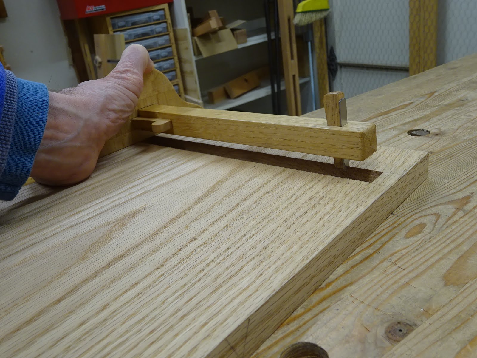
Started out with this marking gauge, but it couldn't reach the third mortise for the bottom shelf
The end of the gauge also hit the "stop" of the dado and couldn't mark the
further extent of  the upper shelf's second mortise
This gauge could get that extent, but would not reach the third mortise for the lower shelf
I ended up using a panel gauge to mark the furthest mortise of the bottom shelf
With the mortises laid out, I bored out most of the waste
Then chiseled from both sides to the layout lines
Note in the above caption that I said "chiseled from both sides".  If you chisel only from the outside and burst through the inside (in the dado), you will not end up with a clearly defined mortise perimeter.  Even though it will never be seen, this is important when it comes time to place the shelf into the dado to mark the extents of the tenons.  A ragged interior edge will lead to a poor layout line for the tenon.
It's important to get good crisp edges both inside and outside
The second challenge that I mentioned earlier was to mark the shoulders of the tenons and I'll get to that next time.  I'll leave it with a picture of how it has to come out and discuss next time how to get there.
Little 3/8" long tenons fit into the mortises, notch at right covers the stopped dado
Until next time ...

Thursday, February 20, 2020

Don't Forget About Vise Maintenance

In August of 2016, I rehabbed and installed a Record #53 E vise on the front of my bench.  Those posts are here and here.  It had worked great for a long time, but lately I'd had a problem.  The "half-nut" wouldn't stay engaged with the screw when I'm using the T-bar to open the vise (that is, opening the vise without using the quick release).  When this happens, as I turn the T-bar counter-clockwise, the front jaw stays where it is.  The half-nut gets pushed out of the thread and pops back down when the threaded rod makes its revolution.

Well, finally it was time to look into it, so I took the vise off the bench.
Record #53E
After cleaning away some sawdust, I got to the screw threads and the half-nut.  The screw threads looked fine, but I still removed a little built-up grunge down deep in the gullets.
Threads only had minor gunk deep in the gullets
The half-nut was a different matter.  I took off the bracket that holds the quick release bar.
Quick release half-nut is down below this bracket
Half nut - doesn't look so bad?  Look again!
One thread cleaned of the thick layer of gunk
And the rest cleaned up
I didn't really need to take the vise entirely off the bench - I could have removed this from below.  But I would have needed to contort my body and, well, you know.

The vise works better now.  Not perfectly, mind you, but better.  I feel like it's too hard to pull the front jaw out and push it in using the quick release, and I don't know why.  I might have to look a little deeper to see if something is holding it up.  But for now, it's working pretty good.

So a word to the wise - clean that vise once in a while.  It's a dusty hobby we've got (even with hand tools) and that stuff gets everywhere.

Thursday, February 6, 2020

Stanley #75 Bullnose Rabbet Plane

One of the tools I was looking for when I went to a tool meet in November was a bullnose plane.  I did find one, but I should have done some research before purchasing, because I really didn't know much about the one I bought.

I picked up a Stanley #75 for $15 and it was in not-so-great shape.
The Stanley #75 Bullnose Rabbet Plane
Bought it for fine-tuning the fit of rabbeted components after assembly
and also for trimming the internal arrises of drawers and carcases after assembly
Unless you know this is a #75, there is nothing anywhere on the plane to tell you what it is (other than the masking tape with #75 written on it).

The plane has 7 parts in total
The upper and lower castings are attached to each other with a screw and washer.  The front part of the upper casting provides the 1/4" of sole that is in front of the mouth.  The top casting can slide a bit on the bottom casting to adjust the mouth opening.
The upper casting has a number that appears to be "38 1/2" cast on its underside.
The lower casting has a "188".  Not sure what either number means.
The lever cap has a number "189" on its underside.
Huh ?????
Back to the castings.  The lower casting was very rough from the manufacturing process.
I later smoothed the sides on sandpaper
The bed was similarly rough, and a little hollow from side to side
I cleaned up the rough sides and the bed with some sandpaper on a flat surface.  And while I was at it, I cleaned up the sole.
The sole was pretty grungy ...
... but cleaned up easily - this is midway through
The problem area of this plane is the lever cap.  First, it was not even close to flat on the underside, and second, it didn't mate with the iron well at all.
Lever cap, showing the hollow spots that mate with tabs on the upper casting
Iron and lever cap removed, looking forward from the rear of the upper casting (towards the toe),
showing the tabs under which the hollows of the lever cap seat
Looking straight on from the toe, showing how the lever cap seats below the tabs
So here's how it works.  After the iron and lever cap are installed, the thumb screw on the lever cap is tightened, lifting the back end of the lever cap.  Using the tabs in the upper casting as a fulcrum, the front of the lever cap is pressed onto the iron to tighten up.  It doesn't seem like the lever cap fits even close to well side to side between the tabs.

The lever cap was in poor shape and only touched the iron on the left side.  The cap had once been painted (or Japanned?), but there was little remaining in the two hollow spots.  So just in case there was something there keeping the cap from seating properly and causing it to tilt as it's tightened, I filed them down a little.  That helped a bit, and I thought of filing the left one more to even out the cap.  In the end, I filed a small amount off the underside of the left tab of the casting and that got the cap nicely fitted left-to-right where it meets the iron.

I also "sharpened" the lever cap, because the leading edge was ragged and shavings could get caught.  It now has a nice leading edge.

The iron was in pretty good shape and just needed the usual cleanup - flattening the back and sharpening the bevel.  The iron is set with a hammer and has been finicky to get it set for a fine shaving.  It seems to move off its setting far too easily.
The iron is about 3 1/2" long
Stamped Stanley logo dates to after 1948, but I suspect is not nearly that old.
They made these planes in the USA until the early 1980's
Patrick Leach says about this plane, "This is a cheap, little rabbet plane, that is very useful in the shop."  However, Paul Sellers pans it, saying "Stanley did make a low-end bevel-down (BD) plane that generally works miserably and that’s the Stanley #75."  There is a great article from Paul Van Pernis in an Early American Industries Association (EAIA) blog, entitled "Stanley's #75 Bull Nose Rabbet Planes from the Model Shop".  If I understand correctly, the "model shop" was basically Stanley's prototype lab.

So far this little plane seems not to work too well.  But how many tools has that been said about before gaining enough experience with them to have them singing properly?  As with many things, time will tell.