Thursday, December 22, 2022

A Little Carving

There has not been a lot of carving out of my shop - just a few isolated instances.  But I've long held that laying out lines properly and cutting to those lines is the bulk of the difficulty in woodworking.  This is true for case work and it's also true for carving.  One big difference is that in carving you have to be ultra-aware of grain direction.

I've only carved letters a couple of times and shapes a couple of times.  I'm really slow at it.  But being careful has helped me with not making firewood.

This time I was making a couple Roubo phone stands and I wanted to add some detail work to each.  The first, in white oak, was to get the initial of the giftee and the second, in red alder, was to get a rosette.  Before working on the real deals, I did some practice runs.
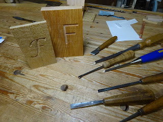
A couple practice runs, testing different lettering fonts and carving techniques 

A couple more potential fonts.
It's far easier to carve the straight F than the script F.

But I liked the script F best, so that's what I went with.  I printed out the script letter F in a 200 or 250 point font and cut out the letter.

The template taped to the white oak phone stand

After tracing the letter onto the wood, I made the first few jabs at terminal points

Didn't get further progress pics of this, but it ended up coming out great.  I will say that the (very old and dry) white oak was far more challenging to carve than the alder.  A couple coats of BLO brought out a nice color in the oak.  And dang it, I don't have a completed picture either!

The second phone stand was a totally different type of carving.  No template for this one, just some layout circles and lines to guide the chisels.  I did a first rosette on an offcut, then did the real thing.

At right is the phone stand with lines laid out.
At left is a rosette I carved a year or two ago just to try it, 
and in the middle is the practice run of the right size on an offcut.

All done (before oiling) - this came out great!

I've gotta say, these were not quick to do.  The woods were hard and I took my time.  No mallet was used - just hand pressure.  I was mentally and physically tired after carving.  When you don't do it all the time, it really takes a lot of concentration to avoid mistakes with grain direction.  Oh yeah, my hand is a bit sore too.  You can always tell that you've done something different from usual by the aches and pains you get.

Thursday, December 15, 2022

Small Two-Drawer Cabinet

This past year I've done more in the shop with new-to-me tools than with building things.  After the last several weeks of working with old tools, I needed to make something.  I have no need for this cabinet, but it satisfied the itch.  It's about 15" deep, 11" wide and about 8 1/2" tall.

The completed cabinet

This is a Paul Sellers project from a few years ago.  As usual, I used some wood that was formerly something else.

The pine for the sides had some very interesting grain (birds-eye pine?!)

The bottom and top have stopped dadoes to house the rabbeted sides.
The sides, top and bottom also have a groove to house a back.
The sides have a mortise to accept a drawer divider,
and drawer runners are screwed to the sides.

First dry fit

After shaping the top and bottom edges, glue-up went smoothly

I really like drawer-making.  Something about the fitting of components just gets me into a nice rhythm.

Fitting the redwood lower drawer front to its opening

Fitting the soft maple drawer sides to the opening

The drawer dry-fit with solid wood bottom nearby

I used 3-4 coats of shellac for the finish, followed by paste wax.
Each drawer pull is a piece of leather stuck through a narrow mortise
and fixed to the inside with screws.

Here are some details of the leather drawer pulls.

Close-up of the leather sticking through the 1/8" wide through-mortise

View of the inside of the drawer front


Close-up of that view showing how the leather ends are affixed

The 1/2" thick solid wood back floats in grooves

The drawer dovetails came out great - what a contrast!

I love it when closing one drawer makes the other drawer push out a bit.  It was a good piston fit.  All-in-all a nice project.  It's good to get back on the horse again after a little layoff.

Friday, December 9, 2022

A Couple Funky Saws

This post is as much a request for information as it is to document these two saws.  If anybody knows something about these saws, please comment.

These were part of an auction lot that I bought at my local tool collector's organization, PAST Tool Collectors.  Sometimes when an auction has multiple items in a "lot", you get some oddballs with the stuff that you really bought the lot for.  In these next two photos, ignore the middle saw - I posted about that one separately.

Top: a little skewback;   bottom: an odd two-sided saw

The other side.  Notice anything odd?

The little skewback has no indication of maker.  Based on its size and the small handle (even too small for my narrow hand), it was probably made for kids.  It has a 15 1/2" tooth line, 8 tpi / 9 ppi, filed rip, and the plate is about 0.030" thick.  But look at the bolt configuration.

Only one wingnut shows on this side (Wait. What? A wingnut!!??)

In the first picture above, you'll notice two saw bolts on the left side.  One of them doesn't go through!  Instead, there is a hole in the plate for the through bolt, and a slot for the second "bolt".

OK, that's weird!

The second saw bolt is just a pin with a slotted head

Is that funky or what!?  Why would that be.  It's probably just a cheap saw, but it doesn't seem like it would save any production costs to use a slot instead of a hole.

One last thing.  Look at the tooth line in that last pic.  These teeth are filed rip, but the rake is typical of a crosscut saw at about 15°!  The teeth are almost perfectly spaced at 1/8", so this saw was probably hardly used and never sharpened.  The plate is still straight as an arrow, so I'll sharpen it (with 0° rake), reshape the handle and see if it cuts worth a darn.

Update: I've now sharpened the saw and it cuts fine.  I left the relaxed rake for the first 1-2" and the rest is filed with 0° rake.  Also, when cleaning up the plate, I found this.

After VERY light sanding I found a little bit of an etch.
"GREAT S...."  (GREAT STATES?, GREAT SAVES?) Just can't tell.

Is that some part of the etch at lower left of "GREAT"

Here it is cleaned up, sharpened and handle scraped, sanded, reshaped and oiled

And I sunk a hex nut and dumped that ridiculous wingnut

The second saw is just plain wacky.  Maybe some of you have come across similar saws or know something about this type of saw.

That's one funky saw!

This saw has no maker's mark that I can find.  The beefy, 0.048" thick plate has about 19" of tooth line and there are teeth on both edges of the plate.  The symmetric handle is "hung" so that the "hang angle" is the same no matter which way you hold the saw.  One side is filed crosscut (top in this pic), approx. 7 tpi.  The other side has teeth filed for something else - maybe pruning.

The two types of teeth

Approx. 3 pairs of teeth per inch, 6 tpi

Sometimes crosscut saws are filed poorly and the result is what they call "cows and calves" - every other gullet shallow, the others deeper.  But I'm certain these teeth were shaped this way on purpose.  What exactly that purpose was is my question.

The handle has a split that goes from the middle of the grip almost to the front-most saw bolt.

See the crack?  No doubt that's what the black tape residue was for.

The teeth are very brittle - some have broken off and I broke another just messing around with it.  I won't turn this into a user - don't even know what it's for.  But the blade might be useful as a cutter in a tapered reamer.  And the saw bolts are nice brass bolts in very good condition.  That'll come in handy.

Saw bolts in good shape

So that's it.  If anybody has any information they could share about either of these saws, I would be grateful.

Update: I spied a saw just like the double-sided saw above in an old Atkins catalog.  It's a pruning saw.  I can see the larger teeth being used for that.  But why it has the smaller crosscut teeth on the other side is still a mystery to me.

Sunday, December 4, 2022

Two Very Interesting Portable Saw Vises, Part 2: Atkins

Part 1 showed the workings of an E. C. Stearns portable saw filing vise.  Today I have one by E. C. Atkins.  This one was more difficult to figure out how it worked, but I was able to find the original patent and it helped to read it a few times.  The patent, combined with studying and playing with the vise, helped me figure out how it is used.

On the left, is written "E.C. ATKINS & CO. IND'P'L'S"
On the right, "IND. PAT. OCT. 22, 1912"

That ridged area in the middle, uppermost in above photo says "SPRAY", for Charles H. Spray, the inventor and patentee.

More detail of the important parts - will discuss them below

I learned from Bob Demers of the Valley Woodworker blog about Datamp.org, a site that helps people find patents related to old woodworking tools and equipment.  It gets its information from the U.S. Patent and Trademark Office.  Based on the patent date, I found the original patent text and drawing (patent no. 1042049).  My saw vise is a little different from the one pictured in the patent.  I guess they made some modifications after the patent application and approval.

Part A is called the base plate and it has provisions to affix the vise to a piece of wood.  In cross section it's shaped like an "L" so that it can wrap around the corner of a piece of wood.  There's a countersunk hole for a screw in the middle of the leg of the "L".  On the other leg there are also two pikes meant to sink into the piece of wood to hold it steady.

I'm getting ready to drill for this screw

Showing one of the pikes with the indent it made in the wood

I'm pretty sure the flat spot just above the pike was meant to be struck with a hammer
(Note: here I have it mounted to the piece of wood incorrectly - the pikes
should get sunk into a face of the board whereas the screw goes into an edge)

It took me a long time to figure out how this thing is supposed to be used.  I read the patent application and reviewed the drawing many times and it was still a challenge.

In my second picture above, part B is the moveable clamping bar that swivels using the "universal swivel joints" at each end.  Part C (also called a clamping bar in the patent) is a cylindrical rod that can rotate on its axis, thanks to its smaller turned ends that fit into holes in the base A.  When clamping bar B is rotated, it comes into contact with bar C and the two bars make up the clamping jaws.  The two arches (D) are springs that put pressure between B and C.  Here's how you set it up.

Ready to put the saw in the vise.
Bar B is in its relaxed position - note position of arches D.

Insert the saw so the teeth just protrude between B and C

Then rotate bar B so it clamps the saw against bar C
(View from other direction)

Now note the position of arches D

And here's a closer picture of the saw clamped between B (behind saw) and C (foreground)

And here I am filing that small gents saw - works nice!

Here's a side view of how the swivel works and clamps a saw plate.

Cylindrical bar C is at left, bar B uppermost, D spring arches to right

In clamping position, B rotates left and down, against C, D arches are up

The patent also said that the arches D can be used in another way to allow jointing and setting the saw teeth.  They can swivel to the downward position shown below so that the tooth line can be raised farther above the clamping jaws.

Saw vise with arches D in jointing/setting position
(screwdriver tip (at left) is pointing to the arch D)

Holding a file as if I was going to joint the teeth.

I'm not sure with this small saw if there would be enough room to set the teeth, but that's not critical.  One last thing: there is supposed to be a piece connected near the screw (the screw that secures the vise to a board) that swings out and helps secure the vise to a board.  This example doesn't have that "dog", as it's called in the patent.

So that's it.  A very interesting tool, to be sure.  I didn't even know these existed, and now I have two.  I might be getting rid of one, though - have to see about that.

Friday, December 2, 2022

Two Very Interesting Portable Saw Vises, Part 1: Stearns

Along with the other tools that I recently bought in an auction lot were these two items that I'd never run across before - never knew such a thing existed.  They're two "jobsite" saw vises, made to be compact enough to carry in a toolkit.  I'm certain they're intended to attach to a saw horse for jobsite sharpening of saws.

The first is by E. C. Stearns.  It's got a screw clamp to attach it to a piece of wood for stability and the clamp swivels out of the way for compact stowage.  The vise clamps a saw in its jaws using a cam mechanism.

E. C. Stearns no. 500 saw vise

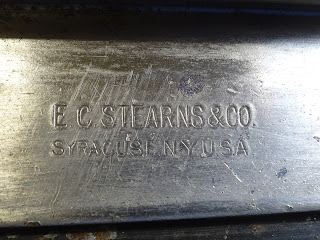
Stamped name shows up great after some cleanup

No. 500

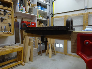
Underside shows the swiveling arm with clamping screw

End view of the vise shows the clamping screw in clamping position

Here it is clamped onto a 2x4 that is held in my bench vise

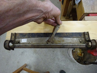
Top view.  I'm holding the cam lever.  Yellow arrows show slots allowing part A to slide
when cam lever is moved to right to squeeze against part B.
Green arrow shows the gap between parts A and B when cam lever is to left.

When lever is moved to right, A is pressed against B and the gap is gone

Here it is clamping a 12" gents saw

And a closer shot

And it works pretty well!  Shown here is an inverted "L" shaped wood piece that the vise
is clamped to; the "L" block clamps in my end vise to raise the work up to better level.

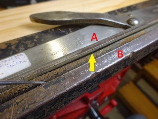
One last thing about this saw vise.  Part A has a hollow area up where it clamps to part B.  And in that hollow is a length of braided steel wire whose diameter (approx. 1/4") is slightly greater than the depth of the hollow.  My guess is that the braided wire has some compressibility and gives a better hold on the whole length of the saw plate.

Dental tool (left) is lifting the braided wire out from where yellow arrow points

This shows how the wire is attached: it's simply stuffed through a hole in each end!

And here's the only problem.  The wire is not taut enough to stay in place in its groove.  I have to be very careful that it's in the groove when clamping a saw plate - otherwise I clamp a big bend in a saw plate.  When researching this, I read that someone replaced the wire with some rubber screening spline (or something similar).  That's an option, but I'm not sure if I want to replace an original part.

This is getting long, so I'll write about the second saw vise in another post.  Until then ...