Wednesday, November 30, 2016

Experiment With Angled Dovetails: Poplar Step Stool

I have a step stool that I made several years ago in my power tool days, based on one I read about (if memory serves) on this blog by a very prolific and inventive fellow.
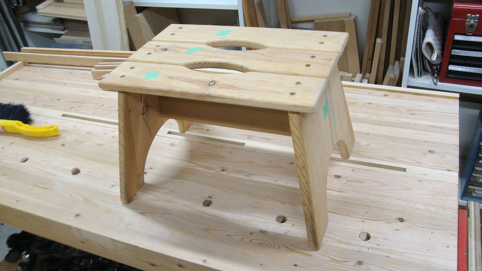
The old step stool

It's been great and I use it all the time.  The legs angle out from the top by about 10°.  The hand holes make it easy to pick up.  But it's just screwed together.  We can't have that, now can we?

I've been interested in trying out angled dovetails.  I want to make a step stool from three boards - a top and two legs - with the legs angled out and joined to the top with dovetails.
Three boards glued up from scraps from my recent chair project

There is a great video on YouTube by "Half-Inch Shy" explaining how to do this type of work.  But my situation is different from the ones he covers.

Turns out my situation is easy.  Once you plane a bevel on the ends of your boards, the layout and cutting of the DTs are practically the same as 90° DTs.  The angle I'm using is about 12°.
Marked the 12° bevel
Pencil lines to help monitor progress
Half way there
Thank goodness for knife lines to guide the way!
Eventually get a good crisp bevel
I marked out 6 tails, starting from a pin that was marked 1/8" either side of the center line.
Penciled in center pin, then stepped off the tails using dividers
Tails marked
This was not as easy as I first thought.  With the beveled end, I didn't want to use my standard DT marker because of it's short registration surface.  So I used a bevel gauge and even here I had to be very careful that the gauge's stock had full contact on the end of the board.
Front of gauge's stock not registering properly on the end
Cutting the tails was straight forward as long as you remember that the base of the cut had to be at the same angle as the end of the board.
Using a backer board to help make straight cuts by lengthening the cut line
When chiseling out the waste, you have to chisel at an angle.  I used my bevel gauge again at 12° to aid with the angle.
Bevel gauge helps guide the chisel angle for the baselines
To transfer the tail outlines to the pin (leg) boards, I had to rig up something to account for the splay angle.
Marking the pin board from the tail board
Cutting out the waste on the pin boards was straight forward - used a coping saw for the bulk and chiseled to the lines.

Gotta stop and talk about a small epiphany I had regarding knifing lines.  I don't knife a single long baseline when dovetailing - I like to knife each waste piece separately.  That means I have to stop the knife before it gets into the keeper wood.  I can't tell you how many times the knife suddenly moves and it's too late to stop it.  But I discovered a technique using my middle finger as leverage to help pull the knife in a more controlled manner.
Knifing the baseline of one waste area
Using middle finger to stabilize the knife hand and enable a more controlled knife cut
There's a subtle difference in the two pictures above, but it's an important one.  Try to ignore my left hand that is holding down the combination square.  By placing the middle finger of my knife-wielding hand on the board I had better control when cutting up to, but not over, the waste line.  I could actually pull the knife using a bit of leverage that the finger enables.  Great stuff!!

OK, back to the project.  After lots of trimming and test fitting I got a decent fit.
First end dry-fitted
Both ends dry-fitted - starting to look like something
Time for some shaping.  I wanted to cut out a half-elliptical shape on each leg to create two feet on each side.  After experimenting with some shapes, I used a French curve to create a template.
Cutting a template
Marking the leg
Then cut out the shape with coping saw and smoothed with rasps, files and scraper.  I also angled the sides of each leg so they were narrower at the top.

For the top, I had marked two elongated holes.  The ends were drilled using a 1.5" Forstner bit in a powered drill (OK, I admit to using a power tool here) and the waste between them was removed with a coping saw, then smoothed with rasps and files.
Starting the hand holes
The above picture also shows the arc that will be shaped on the sides.  No action shots, but a saw, chisel, spokeshave, plane and scraper were used to make and smooth the curves.

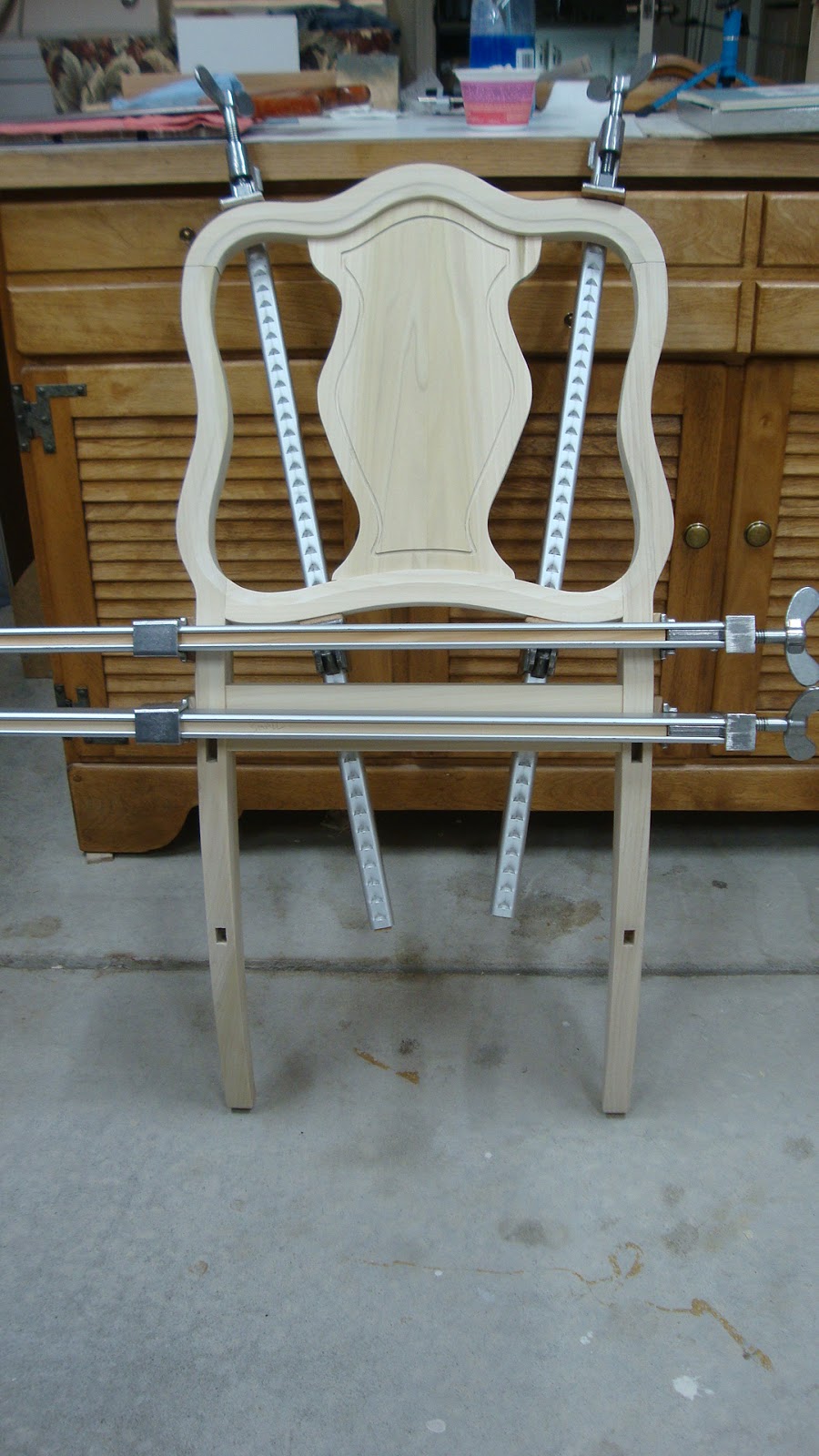
I made some 12° cauls to help with the glue-up.  Coarse sandpaper adhered to the underside of these cauls kept them from crawling up the angled legs when pressure was applied.  I also fitted a couple spacers so that the feet wouldn't be forced towards each other during clamping.
Glue up - see the spacers resting between the feet?
Planing the joints after the glue dried was a little challenging due to the splay angle.  I had to be creative in figuring out how to support the piece.
Position for planing the leg half of the joint
Using the center slot in my bench for planing the top half of the joints
The cleaned up joint - not perfect, but I'm happy with it
I've applied two coats of shellac and after a final sanding it will be ready to be put to use.  And here's your glamour shot.
Thar' she blows!!
A relatively quick and useful project using scrap wood.  The angled DTs were fairly easy - no real tricks here.  I'm going to have to try some of the other types of angled DTs soon.  Maybe on some Christmas projects coming VERY soon.

Wednesday, November 23, 2016

Nana's Dining Chair Rebuild, Part 7: Glue-up and Finishing

With all the joinery, shaping and detail work complete, I could get to the assembly.  The glue-up went fairly smoothly, with a little panic (as per usual) when gluing the front assembly to the back assembly.
Front leg assembly: legs and front rail (note shaped cauls that save legs from dents)
Back leg assembly: legs, seat rail, lower backrest rail, backrest panel and upper backrest rail
After those assemblies dried and a dry rehearsal was done for the full assembly, it was the point of no return.  The lower rails were glued first, then the seat rails were added.  I used the off-cut pieces from shaping the back legs as cauls during clamping.
The whole she-bang
The chair was a little out of square - less than 1/8" - and I adjusted the clamps to get this to about 1/16" before I was satisfied.
The glued up chair
The original chair had arms and I opted not to include them in my reproduction.  The next picture shows one of the arms from the original placed where it would have gone.  It was a two piece arm.
Original arm held where it would have been attached
The upright of the arm was screwed to the side seat rail
The armrest was screwed to the curved portion of the backrest
Anyway, I made the executive decision not to include the arms on my chair.  I thought about how I might prefer to attach them if I had included them - the upright tenoned into a mortise in the seat rail, the top of the upright tenoned into a mortise in the underside of the armrest, and the armrest tenoned into a mortise in the front of the back leg.  Maybe next time.

I added corner brackets that really solidify the chair and add a way to attach the seat.  The angles came out great and they fit like gloves.
Corner brackets added
On to finishing.  First was a coat of clear shellac that would hopefully reduce blotching and make the stain more even.  I took a couple pieces of the original chair to a local paint store and asked if they could match the color.  Turns out a shelf product matched quite well - ZAR interior oil-based stain "Teak Natural".  I gave the chair two coats of that, sanding lightly after each coat dried.  The color didn't look great after the first coat as some places took the stain differently from others.  I think two or three coats of shellac before staining would have been a better idea.  But the color evened out after the second application of stain.
Chair after stain applied
After the stain, I applied two coats of a satin polyurethane and a coat of paste wax.  The chair looked better with each successive layer.
Poly added
Finally, the seat could be attached.
A glamour shot
And how does it feel?
Ahhhh!
Here's the chair next to one of the originals (can you tell which is which?).  Overall I'm very happy with the result.  Stoked that after so long I finally reproduced the chair and that I've accumulated the skills necessary to do it.
Original on left, reproduction on right
BTW, I found out my Grandparents bought this dining set in 1920!  Almost 100 years ago!  No wonder the original chairs that were put together with dowels were a little rickety.  I hope my chair will last as long or longer.

To anybody reading this - have a very happy Thanksgiving.  Savor the time spent with family and friends.

Thursday, November 10, 2016

Nana's Dining Chair Rebuild, Part 6: Some Details

I'm stoked!  Jazzed!  Chuffed (for our British friends)!!

At the end of the previous post, I asked for suggestions about how to add the recess details to the backrest panel and the front seat rail.
Detail work on the original chair
Thanks to the help I got from Ralph, Jonas and Bob, the job got done.  It took two days - one day to think about it and one day to do it - but the job is done.

Yesterday I tried a bunch of things in laying out the patterns.  For the seat rail, I started by drawing points exactly 5/8" up from the bottom, but not straight up - the points were perpendicular to the bottom at each point.  After connecting them with a curve, it didn't look quite right.
Experimenting on the template - not quite right
Then I realized that whoever made this chair originally used the exact same template to mark out the detail as they did for the rail's bottom edge.
A very close match
The original builder probably drew in the shape from the template and then freehanded a powered router with an 1/8" bit.  The small inconsistencies lead me to think it was freehanded.

So I drew the shape on my work piece with my template 5/8" up from the bottom.  Then made many marks 1/8" below that line and connected the points either freehand or with the help of some French curve templates.

For the backrest panel, I experimented with making a template based on the original chair.  I made a rub of the original to get the outline.
Made a rubbing of the original backrest splat
Close-up view
This worked nicely, but I realized that just as the original backrest panel was not symmetric, the detail that I'm trying to reproduce was also not symmetric.  So I ended up generating the curve myself.  I used a compass to scribe a "parallel" curve along the sides 5/8" in from the side.  At the bottom I had to adjust the setting of the compass to account for the tenon.  At the top I had to wing it.  After getting the corners to look right, I marked points 1/8" outside of this shape and connected the dots.
Generating the shape of the recess
Now it was time to knife the lines.  I experimented with making a twin blade cutter, but abandoned the idea.
Thought about making a double bladed cutter, the blades set just over 1/8" apart
I tried cutting freehand the lines for the front seat rail on a piece of scrap.  The freehand cutting was OK, but trying to chisel out the waste was horrible.
First attempt on scrap
This morning I bought a set of French curves, something I've thought about getting many times.  I needed something to guide my knife when cutting the outline of the details.
Using a plastic French curve to knife the lines
This worked well, but was slow as I really didn't want to mess up the parts at this stage.  With the lines knifed in, I needed some way to remove the waste accurately and to consistent depth.  Jonas had commented about making a mini router plane from a block of wood and a screw.  This got me to thinking and this morning I had an idea,

I took a squared-up 1 1/2" x 3" and marked, sawed, and planed a 45° angle on the end.  Then I marked a 1/8" slot on that face.
45° end on a 2x4 with 1/8" (strong) slot marked out
After sawing and chiseling out the waste, a 1/8" chisel fit in the slot so that the body of the chisel was proud of the surface by 1/16" or so.  Then I screwed another piece onto the angled face to lock the chisel in place.
One mini router plane, coming right up!
Side view
Close-up view of the chisel extending down below the base
I couldn't wait to try it, but first I had to chisel out some waste to leave a hump in the middle of the recess.
Chiseling out some waste first
And then - are you ready for this? - I started routing.
Routing out the recess
Holy crap, this was exciting!  And it worked extraordinarily well, though I had to take very small bites and many passes.
Look at the little curly shaving!
I ended up going about 3/32" deep and used a piece of sandpaper wrapped around a plastic card to clean up the recess a little.
Front seat rail done
Backrest panel done
Like I said - STOKED!!

BTW, does anybody know what this type of detail is called?