Thursday, May 26, 2016

Sketchup Model of The Joiner and Cabinet Maker's Chest of Drawers

A few month ago I read the Lost Art Press (LAP) book "The Joiner and Cabinet Maker" and really enjoyed it.  As many of you know, this book was originally written in 1837 and follows Thomas through his apprenticeship in a woodworking shop and through three projects he builds.  The original author is unknown.
Photo from LAP website
In addition to the original text, Chris Schwarz and Joel Moskowitz give some historical perspective and Chris gives his account of building the projects.

While I have no plans (at least not right now) to build any of the three projects from the book, I wanted to create a Sketchup model of the Chest of Drawers in case I decided to try it later.  Working on this model off and on for a few months, I used the Chris' descriptions (not the ones from the original text) in the book to guide me and when things were unclear I was helped by the book's many photos.
Joiner and Cabinet Maker's Chest of Drawers
I contacted LAP about whether or not I could offer my Sketchup model to others and they said it was OK.  Since I contacted them, they offered their own Sketchup models of the projects from the book.  For the chest of drawers, there are a few differences between their model and mine and I'm not certain which is correct.

One difference concerns how the back is let in to the case.  In my model, the rear-most of the three top rails (that are joined to the sides with half-blind dovetails) is flush with the bottom of the rabbet cut in the sides.  In the LAP model, this rear-most top rail is flush with the back edge of the sides and has a rabbet of its own to accept the back.  Pics from the book show I have the top rail position right, but that leaves the frame and panel back flush with the top of the rail - not let in to something.
Upper left of back of chest
The LAP file includes some front to back members between top rails.  These would keep the top drawers from tilting down when they are pulled out, but these front to back pieces are not mentioned in the text that I can find.
LAP file, top removed to show top rails and front to back pieces
One final thing I'm confused about is how the glue blocks are installed on the feet.  The LAP file shows solid strips of 1" square blocking in three directions, though the book shows three segments in different grain orientations for the vertical glue block.
LAP file, underside of chest looking at inside foot detail
The grain on the feet runs horizontal, so the upper two glue blocks can be glued directly to the feet. But one of them must be glued cross grain to the underside of the chest.  I don't know how that is dealt with.  For the vertical glue block, if I understand Chris' explanation, it will be in three sections as follows: the top section has grain oriented horizontally and has end grain to the right half of the foot, the second section has grain oriented horizontally and has end grain to the left portion of the foot, and the bottom section has vertically oriented grain which is cross-grain glued to the feet members.  This makes it so that there is minimal cross-grain gluing and the tougher end grain that wears well will be at the bottom of the cabinet touching the floor.  The next picture explains this (hopefully).
Foot glue block detail showing orientation of each piece
My intention is to share this model with others who may want to use it.  I think the only thing I'm missing is the knobs.  Oh, and I haven't shown any dimensions - you'll have to use the tape measure tool for that.

If I can figure out how to attach a Sketchup file to this post I'll do it.  Otherwise, you can contact me. I'm not sure how to keep 'net anonymity (so that nobody gets their e-mail address stolen) when contacting.  Any suggestions?

EDIT 27-May-2016: There's no way to attach the file to the blog post, so I've added a "Contact Me" button on the blog.  You can send me a message and I'll reply via e-mail with the Sketchup file.

Wednesday, May 25, 2016

A Couple More Woodworking Tidbits from the Louvre

I didn't have nearly enough time to spend at the Louvre, but in the ancient Egypt area I found a few other interesting things.  First was the method of sealing a sarcophagus.  The following picture is the bottom portion of a sarcophagus.
Base of a sarcophagus - note mortises
Here is a closer view of the center mortise.  In this view you can see more clearly a hole for a peg that will be used to lock a tenon in the mortise.
Mortise and peg hole
And here is the tenon with matching peg hole on the upper portion of the sarcophagus.  Note that the grain direction of the tenon is perpendicular to the grain that it is protruding from.  This would make it a "loose tenon", but I'm not certain how it was attached.  Maybe some kind of glue, but maybe there was another peg - don't recall.
Loose tenon?

Another item in that area was a standard rectangular coffin.  The corners were mitered with a peg going through both pieces across the miter, as you can see in this picture.
From above, looking down at one corner: broken upper section with peg protruding
But interestingly, the 45° miter did not extend all the way to the top.  On another corner, you can see that the top transitions into a butt joint.  It was mitered almost all the way from bottom to top, transitioning to butt joint in the top 2-3 inches.  In the picture below, see if you can pick out the peg joining the mitered sides.  In the above picture I believe the wood was broken at the peg hole, an obvious weak spot.
Top of miter transitions to butt joint
Lastly, I wanted to share some pictures from many centuries later of "Scientific Instruments Used in the 17th and 18th Centuries".  Although these were called scientific instruments, I'd bet that most woodworkers had at least some of these instruments in their shops.

Protractor, dividers, squares
Three pronged caliper?  Not sure what this would be used for.
Protractors, dividers, squares, angle finders
Does that bottom square remind you of one of Schwarz' logos?  Great stuff.  It was a real thrill to see these things in the museum.

Saturday, May 21, 2016

A 3500 Year Old Chair

I'm not much of a traveler, but last week my wife and I went to Paris on vacation.  When I have gone places I've found myself marveling at the old architecture.  There's something about 1000 year old structures that strikes awe in me.  How in the heck did they do that with the tools available at the time?  Incredible!

The Louvre is one such place.  It is an approx. 900 year old structure with a lot of history, and has housed great works of art for 100-200 years now (not certain how long).  The point of this blog post is something I saw inside the Louvre.

While going through an area with ancient Egyptian artifacts I spied some old furniture that was made about 1500 B.C. - that's 3500 years ago for those of you who are counting!  What really struck me was how the basic joinery techniques that we use today have not changed.  Take a look at these stools (or backless chairs).  The first has tenons on the legs that are housed in through-mortises in the seat frame.  Look at the carved feet.  The claws are inlaid (sp?) ivory.  All this with bronze tools, most likely.
Note the leg tenons showing through the seat frame
The second stool still has its seat weaving in place (I imagine it's not the original weaving).  On this stool, the legs have through mortises for the tenons of the seat rails.  The mortises for the front and back rails are off-set above the mortises for the side rails.  The tops of the legs are nicely rounded over.
I couldn't tell if the tenons were wedged
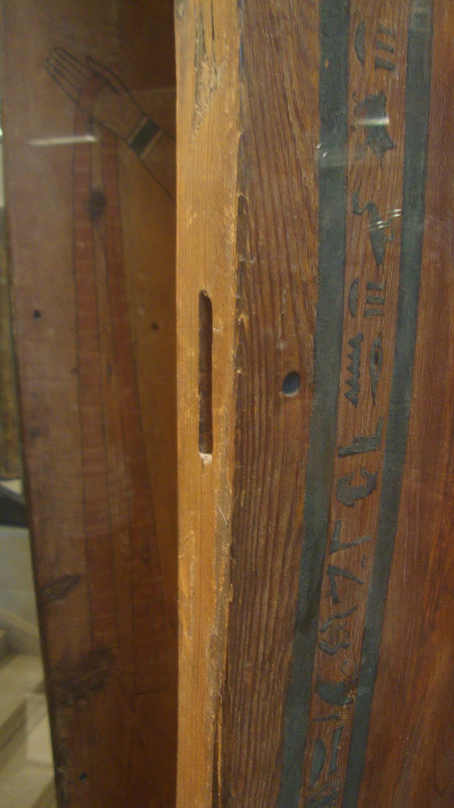
Those were interesting, but what I really want to write about is this chair.  I was dumbfounded!
The 3500 year old chair - so much like good sound construction of today!
The construction is incredibly similar to the dining chairs I recently completed.  Lower and upper rails attach to the legs.  Above the seat, the back legs angle back to become the frame for the backrest. Two backrest rails house a single vertical slat - and the backrest rails are curved for comfort!

The next picture shows the joinery detail of the upper seat rails to a front leg.  You can clearly see the through tenons protruding slightly.  It is possible that the one on the right is wedged, but I couldn't tell for sure.  The left one does not look wedged.
Close-up of a front leg upper rail joinery
With the through mortises, the front and side rails look to be off-set a little with the front rail being higher.  It's hard to tell from the picture (I couldn't get close enough to the chair), but to get the rails at even heights it's possible that the front rail tenons were off-set (to effectively lower the rail) so that the rails could be even with each other.

Just below that was where the lower rails joined with the leg.  The tenons are not through tenons. Why would they have done through tenons on upper rails, but not on lower rails?  Especially when these lower rails are off-set too.
Close-up of a front leg lower rail joinery
The back legs were joined to the upper seat rails the same as the front - with through tenons.  But the more interesting thing for me about this picture is the shaping of the back leg into the backrest.
See the through tenon and the transition from lower leg to upper leg / backrest
The following picture gives a good view of the shaping of the upper portion of the back legs.
View of the chair from the opposite side
Here is a closer view of the back leg transition to backrest.  You can see the through tenons from each seat rail.  The backrest rail, though, does not have through tenons.
Back leg joinery detail
That leaves me with the backrest.  It's interesting that the legs are tenoned into the upper backrest rail, rather than the opposite. That's one difference between this chair and my dining chairs.  I see the lower backrest rail coming away from the right leg a little bit.  I can't tell for sure, but it might be a double tenon.
Backrest detail
Finally, and this really impressed me, this view of the backrest from above shows the gentle curvature of the backrest rails.  These people had all the details to make a chair comfortable and durable.  One can only conclude that they'd been making chairs for at least a couple centuries (maybe more?) to arrive at this design.
Note the gentle curve of the backrest rails
The only information available on this chair was in the cards in the display.
Info cards
Using Google Translate gives the following loose translation into English: "Objects from most of the western cemetary Qurnet Murai (opposite Deir el-Medina). Middle of the 18th dynasty (1450 B.C.), age at which we put in the tombs of the furniture that really served."  [Per Wikipedia, Deir el-Medina was "an ancient Egyptian village which was home to the artisans who worked on the tombs in the Valley of the Kings during the 18th to 20th dynasties of the New Kingdom period (ca. 1550–1080 BC)"]

(Update 25-May-16: a better translation from a kind person in France is "Items mostly from the western cemetery of Qurnet Murai (opposite Deir el-Medinch). Middle of the 18th dynasty (about 1,450 BC), a period when they still placed furniture that had really been used into tombs.")

I'm totally blown away by this chair!  I'd love to see the tools available to the craftsmen 3500 years ago.
Next time I complain about not being able to get perfectly square stock I hope someone kicks me in the ass.  There probably wasn't a truly square piece on this chair.  And if I ever blame my tools again I just have to think about what tools were available 3500 years ago.  How sharp an edge do you think they could get on bronze?  Without diamond plates?  Or good flat reference surfaces?  Or honing paste?  How easy was it to saw with bronze saws?  Or sharpen them without hardened steel saw files?

Amazing!

Friday, May 6, 2016

New Scrapers and Fixed Pax Rip Saw Handle

Another item on my "to-do" list was to make some new scrapers from the blade of a horribly crappy Craftsman dovetail saw that I had gotten some years ago.  I had taken the saw apart a few months ago and it has been sitting in a drawer since then.
Dovetail saw parts
I filed off the teeth with the saw tooth jointing jig, holding the blade in the vise.
Filing off the teeth
After measuring about halfway along the length and marking a line, I sandwiched the blade between two pieces of scrap wood and used a hacksaw to cut it in two.

Sawing the blade in two
After that I cleaned up the edges with files and sharpened as I would any scraper.  I didn't have high hopes about this steel and how good of a scraper it would make, but I got a decent edge and some nice shavings.
Using the new scraper
Time will tell whether these scrapers hold up.  Maybe I'll shape them further and used them for curved work.


Last Friday I wrote about the loose handle of my Pax 26" rip saw.  "Loose" is a bit unclear - it took some force to move it, but it would move in use, which was quite annoying.  Here's the problem: the holes in the plate are 5/16" diameter, the holes in the handle are just under that at 19/64" and the saw bolts thread major diameter is 3/16".  So there is almost 1/16" play between the bolts and the holes in all directions.
Wanted to shim the bolts to fit the holes better
I ended up getting some nylon spacers from McMaster-Carr that were 5/16" OD, 3/16" ID and 1 3/16" long.  Each piece could make two shims.
Nylon spacer
I knew when I got these that they would fit the saw plate holes and that the bolts would fit in the ID (and they did), but I also knew they would not quite fit the handle holes.  So I had to modify the OD slightly and I did this using the scrapers I had just made.  I have a fixture with a V-groove that I use when planing square stock into round stock and that worked well to hold the spacer while scraping.
Scraping the spacer to reduce the outer diameter
Once the diameter was reduced enough, I fit the spacers into the handle holes.
Four of five spacers fit into the holes
Realistically, two or three well-placed shims would have been enough, but I decided to go for all five.  Knowing that today's saws are produced with CNC mills, I was sure the handle holes and plate holes would line up perfectly.  If not, it might have been more challenging to put the saw back together with all five holes shimmed.
Putting it back together
All that was left was to screw the handle back on.  One thing I know for sure, now - that handle is not going to move at all ever again!

Thursday, May 5, 2016

Flattening the Stanley #6 Shooting Plane

A couple weeks ago I noticed that my #6 that I use as a shooting board plane was not exactly flat on the sole.  Holding a straightedge across the bottom revealed quite a gap.  I didn't measure the gap at the time, but when I sharpen the plane and made test cuts on the edge of a 1/2" thick board I got a much thicker shaving in the middle of the plane than at the sides.

To start the job, I made sharpie marks across the sole and got out my plate glass reference surfaces that have sandpaper glued on.  Eighty grit on one plate and 180 grit on another.
A few minutes on sandpaper reveal the low (darker) areas
After a little time on the 80 grit paper that sheet was worn out and I had no more paper in that grit.  So I went to the 180 grit and went through a few sheets over the next half hour.  Most of the sharpie marks were gone, but more importantly I got a nice flat surface around the mouth.  Here is a photo of the sole of the plane looking from the heel to a straightedge laying across the sole about an inch ahead of the mouth.  Just the slightest hint of light.
Looking down the sole - very little light coming through
I have a set of feeler gauges that I bought many years ago from an auto parts supplier.
Cheapie set of feeler gauges
The smallest gauge in the set says 0.0015" on it, so I tried to fit it under the straightedge to measure the gap in the previous photo.
0.0015" (or 0.038 mm) gauge
It didn't fit in the gap, but I thought something was not right so I measured the gauge.
WTF??!!  0.0060" !!
You know what Belushi said to Flounder in the movie "Animal House"  -  "Face it Flounder, you f---ed up.  You trusted us."  Maybe I won't trust these gauges again without verifying them first.  Well, the next larger gauge was 0.003" and I verified it.  It didn't fit in the gap and I'm comfortable that 0.0015" also wouldn't fit.  Maybe 0.001" would fit, but I'm OK with that.

After having flattened the sole, I tested it on the edge of a half inch board and got consistent shavings all across the sole - left, center and right.  Then the obligatory test cut using the shooting board got nice shavings (with freshly sharpened blade) in cherry.
Fluffy end-grain shaving
One problem, though.  The end grain did not come out square to the reference edge.  I had to shim the work piece in the shooting board to get it to square.
See the paper shim (double thickness) between the work piece and fence?
Arrgh!  It's always something ...

EDIT, Added 06-May-2016

Ralph of the "Accidental Woodworker" blog suggested in the comments below that my shooting board fence might not be square to the plane sliding track.  Well it didn't take long to find out he was right.
Checking the shooting board fence for 90°
A closer picture shows the gap on the right.
Tiny gap on the right side, none on left
It's hard to imaging how this could be since the fence sits in a dado that was created with one wall square to the track.  But wood moves and compresses.  The fence is made from poplar and the rest of the board from pine - both very soft woods.

So I tried a couple of things.  First, I checked the 90° wall of the dado.  It didn't seem perfect, so I knifed another line about 1/2 mm away and chiseled a new wall.  When the fence was re-installed, it was still not square to the track.  That meant that the fence had to be adjusted.  So for my second idea, I shaved off a little from each side of the fence and re-fit it to the dado.  At first I took full length shavings from both edges, thinking that I shouldn't change the angle of the wedge-shaped fence.  The shavings showed where the fence had compressed against the dado walls, but the problem persisted.  So I shaved a little more off the left side of the fence, primarily the part that extends past the base of the shooting board.  I was concerned that the fence wouldn't match the angle of the dado now, but this worked and the board is now shooting squarely again.  No pictures, unfortunately.

Tuesday, May 3, 2016

Chisel Sharpening - Jig For A Jig

Yesterday it was time to sharpen my chisels.  I've been doing this by hand on the diamond plates, but I have a tough time getting the cutting edge square to the sides of the chisel.  This is especially true on smaller chisels.
Right side of this 1/2" chisel is shorter
I have a jig for sharpening - the Veritas honing guide - but there are problems with it.  There is no good way to ensure your chisel is set straight in the jig.
Is it straight?  Or is it not?
The other problem is clamping the chisel in the jig to get the right bevel angle.  I eyeball the chisel in the jig against a bevel gauge set at 30°.
Bevel gauge behind honing guide
This works OK, but it's slow and I still have the problem about whether or not the chisel is straight in the jig.  So I made a jig to help in this process.  I took a piece of hardwood and cut stopped grooves of 5/8", 1/2", 3/8" and 1/4" widths.  These grooves are square to the end of the board.  The length of the grooves is equal to the distance the chisel sticks out of the honing guide when it is set properly to sharpen at 30°.
Jig in progress
To use the jig, I set the chisel loosely in the honing guide.  Then set the end of the chisel in the jig so that the sharp end bottoms out at the stopped end of the groove.  This ensures the proper projection to hone at the 30° angle.  Then I make sure the honing guide butts up to the end of the jig (this ensures the chisel is square to the jig) and tighten the clamp.
1/2" chisel bottomed out in groove, honing guide butted up to jig, ready to clamp
This is not perfect due to a little slop in the jig and issues with the honing guide clamp screw, but it works pretty well.  The 1/2" chisel came out perfectly square after sharpening.
That's as square as I'll ever need it
I still plan to sharpen by hand, but every once in a while I'll use this jig with the honing guide to bring things back to square and to the proper bevel angle.