Wednesday, November 6, 2024

Making a Cap Iron Screwdriver

How do you spell cap iron anyway?  Two words? One word? Hyphenated?  Maybe I should just say chip breaker.

Recently I saw a Bill Carter video and on his bench was a cap iron screwdriver.  Seems like I'd seen him talk about it (though I can't recall where) and he espoused the virtue of using it rather than using the lever cap to uncouple the cap iron from the plane iron.  I've been using my lever caps for almost 15 years without any chips to the lever cap, but I thought I'd make a special screwdriver for this task.

I roughed out the shape on paper and found an over-length piece of scrap wood to use for the handle.  I also found an old hinge leaf to shape into the blade.

Some initial thoughts and some steel for the blade.
These weren't the final measurements, but they were close.

I started with some careful layout on the wood blank and removed a bunch of material with saw and chisel.  Then it went on my bungee lathe to turn the ferrule post and the "waist" of the driver.

Shaping the front end of the handle on the bungee lathe

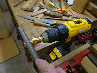
While I had the bungee lathe set up, I also turned a small piece of dowel so that one end would fit tightly into a brass plumbing adapter and the other end would fit into my drill.  The plumbing adapter would later become a ferrule.

Brass barb to thread adapter (most of barb end has already been cut off)

At first I thought I'd be able to file the barb end with it chucked into my drill, but it turned out to be far easier to file it while clamped in a metal working vise.

Here's the adapter with mandrel stuck into one end

And chucked into the drill

Filing while in the drill was not optimal - too much flex of the drill

So I just filed it while held in a vise

then sanded and polished it smooth and shiny in the drill

I cut off 5/8" length of the smoothed brass adapter and fit it to the ferrule post.  I sawed and filed a slot in the post for a good fit to the screwdriver blade.  I didn't get any pictures of it, but I filed the piece of steel hinge to the proper shape to fit into the ferrule post.  It's 5/8" wide at the business end to fit a cap iron screw full width.  It's a bit wider where it meets the ferrule and fits that nicely with no sharp edges protruding.  I also rounded the tip of the bit, since the slots in cap iron screws are made with a circular blade and are a little deeper in the center than at the ends.

Put a slight curve on the tip

After several coats of shellac, sanding between some coats, then a rub with 0000 steel wool followed by some paste wax, the handle feels very nice and looks great.

And here it is, ready for service

Fits perfectly

I did have to grind the tip a little to get a good fit in the slot.  The hinge metal was about 3/32" thick and the slot is about 1/16" wide.

Another very satisfying project for sure.  Now I'll never have to worry about the lever caps chipping - that is, if I can break my old habit of using the lever cap and start using this new screwdriver!


Saturday, November 2, 2024

On Older and Newer Starrett Combination Squares

A few days ago I wrote about fixing up a Starrett combo square that I found at a garage sale.  It had all three heads - 45/90, protractor and centering - but I could only get the centering head to clamp the rule securely.  Turns out it was user error and I'll explain a bit here about that.

Here's the 45/90 head with rule in place

The clamp screw, spring and nut

You can see at the left end of the clamp screw, there is a raised tab that fits into the groove in the rule.  When the clamp nut is tightened, the tab pulls the rule tight in it's slot in the head.

The groove in the rule

Here's where I went wrong.  Note the little nub on the side of the clamp screw, roughly centered along its length.

The nub in question

This nub's purpose is twofold: to keep the clamp screw from sliding too far down in it's hole and to keep the clamp screw from rotating in the hole.  But there's a catch.  It turns out on older Starrett combo squares (and accessory heads), there's a small recess cut on the side of the shaft into which the clamp screw goes.  This recess extends from the bottom of the slot (in which the rule slides) towards the clamp nut for about 1/8".  I tried to get that in a picture, but it's very tough to photograph due to its location.

Looking down into the rule slot of the 45/90 head
The camera is actually a bit to the right of being straight above the hole
(the round hole is for the clamp screw)

Closer-up pic showing the recess for the nub

An even closer pic - if you use your imagination, you can see the recess.
We're actually seeing the bottom of that recess.

So it turns out that the clamp screw only goes into the head one way.  The nub has to go into that recess.  If it's turned 180 deg, the nub gets caught on the bottom of the rule slot and you can't tighten the rule enough.  Turned the proper way, the clamp screw goes 1/8" deeper in its hole and you can clamp the rule tightly.

I'm glad I figured this one out - I was considering filing off the nubs on two of the clamp screws!

Now, here's a newer Starrett combo square for comparison.  This was one of the only high end tools I bought new when getting started, and like all Starrett stuff it's been great.  It's probably 10-12 years old now.

The clamp screw, a special washer, spring and nut

There is no nub on the newer clamp screws.  Instead, there is a flat milled on opposing sides of the clamp screw and the washer's hole has two flats that match the flats of the screw.  There are two tabs on the washer that fit into recesses in the head casting and that is the mechanism that keeps the clamp screw from turning in its hole.

A flat milled on the clamp screw
(the washer is in place, but isn't easily seen in this pic)

A tab on the washer up into its recess

So the clamp screw can go into the head two ways.  There is no nub to require it to fit only one way.  I hope this clarifies the way these squares clamp the rule and that it helps someone who is up against the same issues.