Back in August or September, I found a few interesting things at two estate sales. The combined haul was not huge, but included an almost complete set of auger bits, a 10" brace, an 18" auger bit extension, 3 chisels and some used and unused hacksaw blades.
 |
| The modest haul was still worth the time |
This post will cover the boring tools and a follow-up post will cover the chisels.
The auger bits comprised an almost complete mixed-maker set. They were all fairly rusty, but they cleaned up nicely using the rust removal formula I wrote about a couple months ago. There was at least one bit that was too far gone to be useable - it's cutting spurs were bent horribly and there wouldn't have been enough left to be functional if I had filed them smooth. A couple others had spurs that were about even with the cutting lips, so I filed the cutting lips down to allow the spurs to score wood before the lips would start removing material. Filing the lips that much is not optimal, but at least they'll cut a hole now. And if I'm careful, the hole will be reasonably clean. Here are the sizes and makers or markings (a slash "/" denotes different lines of markings):
- 3/16 No markings (unusual size - not sure I've seen one before)
- 4/16 ACRABORE / TAYLOR-GUEDE / MADE IN U.S.A.
- 4/16 RUSSELL JENNINGS
- 6/16 CLEAN CUT / TRADEMARK
- 6/16 No markings
- 6/16 GILMORE SPECIAL (This one is beyond restoring)
- 7/16 ACRABORE / TAYLOR-GUEDE / MADE IN USA
- 8/16 IRWIN / USA
- 9/16 GREENLEE / ROCKFORD ILLINOIS / MADE IN USA / No. 22
- 10/16 IRWIN - U.S. of A.
- 13/16 GREENLEE / ROCKFORD ILLINOIS / MADE IN USA / No. 22
- 14/16 THE JAMES SWAN CO. / SEYMORE CT, U.S.A.
- 15/16 THE JAMES SWAN CO. / SEYMORE CT, U.S.A.
- Small Expansive Bit (Small Cutter Only) CLARK / CONVALCO / EXPANSIVE / U.S.A.
- Large Expansive Bit (Long Cutter Only) HSB & CO. / OUR VERY BEST
The missing sizes were 5/16", 11/16", 12/16" and 1". By coincidence, I found a C. E. JENNINGS & CO. No 10, 11/16" bit in great condition at a garage sale within a couple weeks of finding these.
 |
| The former owner had made this neat holder from a big chunk of wood |
A few of these bits needed remedial attention. They hadn't been taken care of and had a hard life.
 |
The Gilmore Special 3/8" bit looked like it had been down a kitchen
sink "dispose-all". The spurs are hopelessly dubbed over and the
lead screw threads were beyond repair. |
 |
The 1/2" Irwin - USA bit was in rough shape. The left spur has been
filed here, the right spur is dubbed over and is next up for filing. |
 |
Because I had to file the spurs down, the cutting lips also needed to be
filed so they wouldn't start cutting until after the spurs engage.
Not optimal, but it does work now. |
 |
| Here's the lot of them, all cleaned up |
The smaller of the two expansive bits was a Clark. I'd never seen one so small. It can bore holes from about 1/2" to 1" diameter. The expansive bits I'd seen previously were for boring holes larger than a typical set of 1/4" to 1" diameters. I'm guessing that this bit was made for people who didn't want to buy a full set of bits.
 |
| The Clark (below) and the H.S.B (above) |
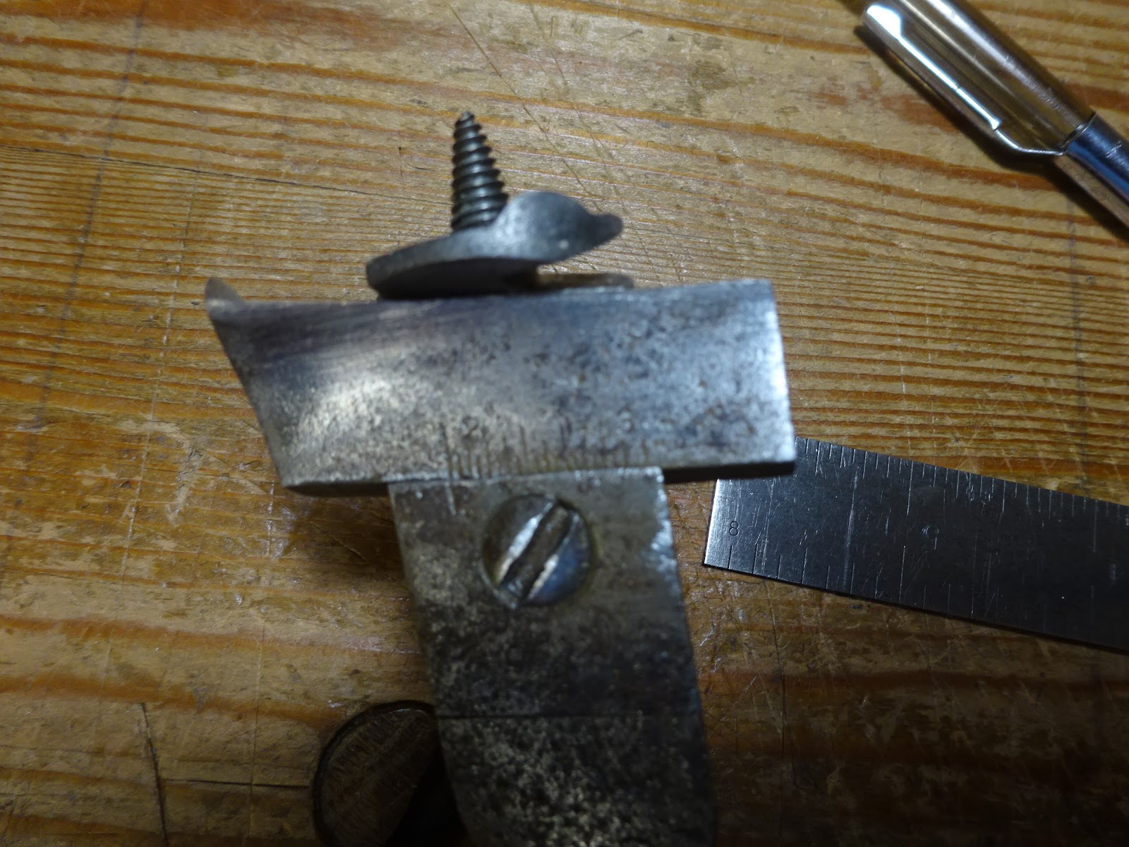
There is a problem with the Clark bit. The spur on the moveable arm is bent inward a little. This means that it might get stuck in a cut because the top of the spur cuts a smaller diameter than the rest of the spur will fit into. I tried to straighten the spur, but didn't get it much better, if at all - I was too worried about breaking off the top of the spur.
 |
You can see the problem in this picture.
Note how the tip of the spur bends in a little. |
 |
I tried tapping the spur to get it to proper shape, to no avail.
I may try to heat it to make it more malleable and then tap it. |
The larger expansive bit is from Hibbert, Spencer and Bartlett and it will cut holes like all the other expansive bits I've seen: about 1 3/4" to 3". The smaller cutting arm was not present. The spur on the main body is a bit short - about at the same level as the cutting lip on the main body. But it will still cut a hole because the spur on the moveable arm is plenty long.
 |
| The business end of the HSB expansive bit |
I've sharpened both of these bits and they'll cut, but they could be better.
The auger bit extension that I found looks like it was user-made. There is no maker's mark, it's not exactly straight and an auger bit just fits in the end with no locking mechanism at all. It was really rusty as found, but I cleaned the rust off and it looks better.
 |
| The auger bit extension |
 |
| The business end - looks to be hand forged |
 |
| Probably hammered around another auger bit's square tapered shank |
 |
| A defect |
I bought this because recently when making a chair, I couldn't fit my other bit extensions through a 5/8" hole in the arm to bore a hole in the seat. My other bit extensions have diameters of 11/16" where they hold an auger bit. But this one has a diameter of about 9/16", so it would have worked in that instance. Too bad I found it a couple weeks too late!
 |
| The 9/16" extension above, 11/16" extension below |
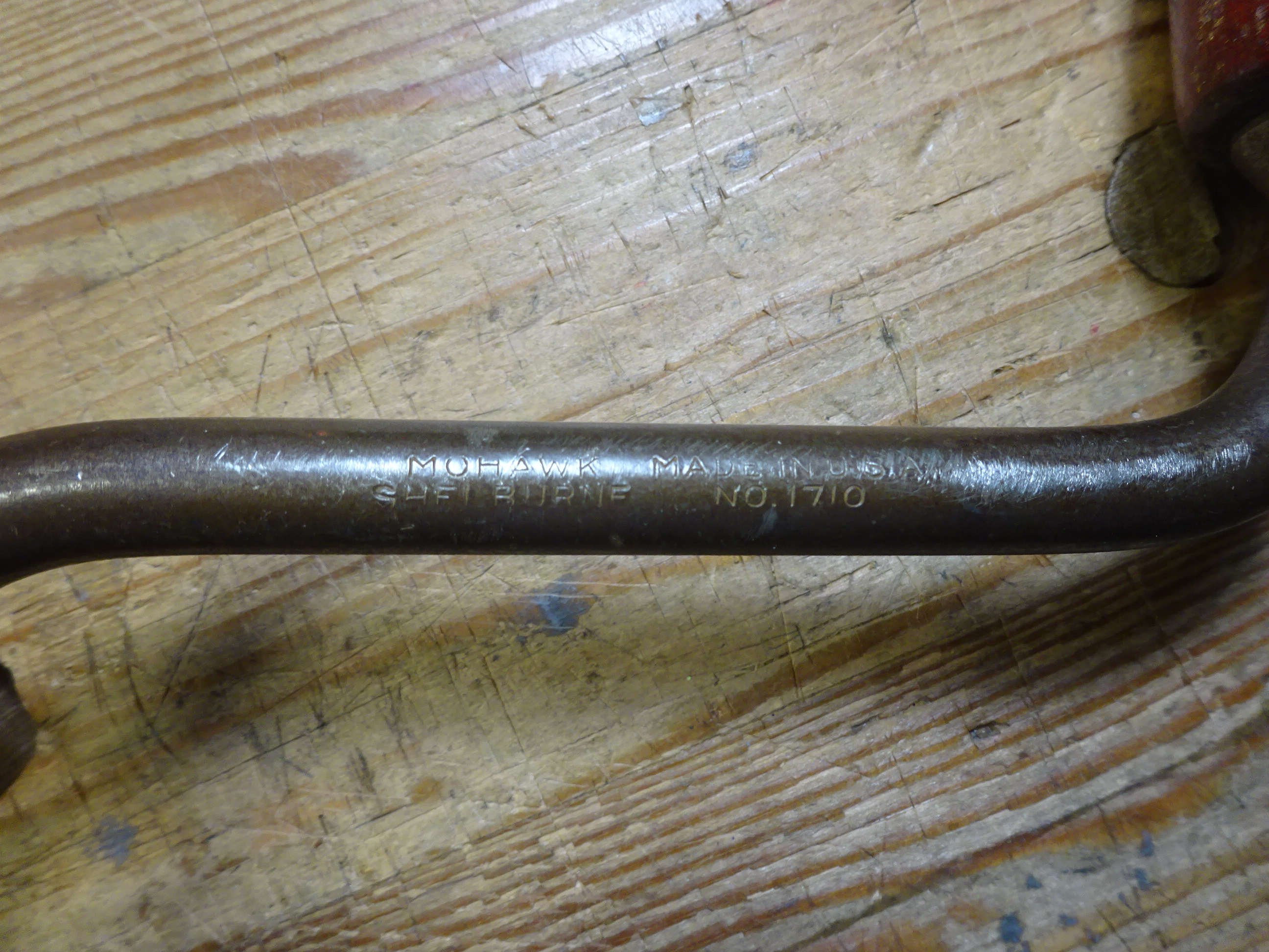
Lastly, there is this 10" sweep brace. I still need to clean it up, but I can tell that it'll clean up easily and work perfectly. I don't know anything about this brand.
 |
It's marked:
MOHAWK MADE IN U.S.A.
SHELBURNE NO. 1710 |
 |
| I can see the ball bearings in this ring below the handle |
That's it for this post. Next time I'll write about the chisels - they were quite interesting.